iSunergy YCX50A
iSunergy MPPT Solar Charge Controller User Manual
Model: YCX50A
1. Introduction
This manual provides detailed instructions for the installation, operation, and maintenance of your iSunergy MPPT Solar Charge Controller. This intelligent regulator is designed to efficiently manage power from your solar panels to charge various battery types, ensuring optimal performance and longevity of your solar power system.

Figure 1: iSunergy MPPT Solar Charge Controller (Front View)
2. Product Features
The iSunergy MPPT Solar Charge Controller incorporates advanced technology and robust features for reliable solar power management:
- Advanced MPPT Technology: Efficiency no less than 99.5%, with maximum conversion efficiency of 98%. Ultra-fast tracking speed and guaranteed tracking efficiency.
- Large-screen LCD Display: Displays charging and discharging current, cumulative power generation and discharge power, and temperature.
- Adjustable Parameters: Customizable charge and discharge parameters with power-off memory function.
- Dual USB Output: Maximum current of 2.5A, supporting mobile phone charging.
- Comprehensive Protections: Built-in short-circuit protection, open-circuit protection, reverse protection, and over-load protection. Features reverse current protection and low heat production for self-recovery without damaging the controller.

Figure 2: Key Features and Components
3. Setup and Installation
Proper installation is crucial for the safe and efficient operation of your solar charge controller. Please follow these steps carefully:
- Mounting: Choose a well-ventilated, dry location away from direct sunlight and moisture. Ensure sufficient space around the controller for heat dissipation. The controller has built-in mounting panels for easy installation.
- Wire Sizing: Use appropriate wire gauges for all connections to prevent overheating and voltage drop. Refer to local electrical codes and the controller's specifications for recommended wire sizes based on current and distance.
- Safety Precautions: Always disconnect all power sources (solar panels and battery) before making or breaking connections. Install appropriate fuses or circuit breakers between the solar panel, controller, and battery.
4. Wiring Instructions
Follow the wiring sequence below to ensure correct and safe connection. Always connect the battery first, then the solar panel, and finally the load. Disconnect in the reverse order.
- Connect the Battery: Connect the positive and negative terminals of the battery to the corresponding battery terminals on the charge controller. Ensure correct polarity.
- Connect the Solar Panel: Connect the positive and negative terminals of your solar panel(s) to the corresponding solar panel terminals on the charge controller. Ensure correct polarity.
- Connect the Load: Connect your DC load (e.g., LED lights, DC appliances) to the load terminals on the charge controller. Ensure correct polarity.
- USB Output: The dual USB ports (OUT DC5V 2A) can be used to charge compatible USB devices.
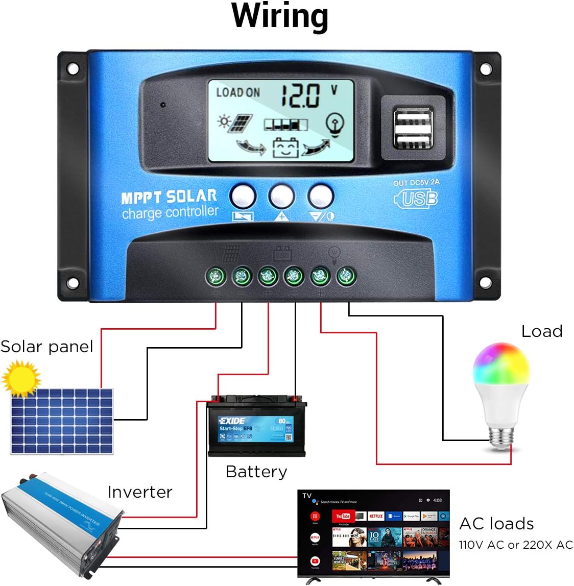
Figure 3: Standard Wiring Diagram

Figure 4: Detailed Connection Points
5. Operating Instructions
The controller features an LCD display and three buttons for operation:
- Menu Button: Press to cycle through display screens and enter/exit setting modes.
- Up Button: Press to increase values or navigate up in menus.
- Down Button: Press to decrease values or navigate down in menus.
5.1. Display Information
The LCD cycles through various parameters. Press the Menu button to manually cycle or hold to enter settings.
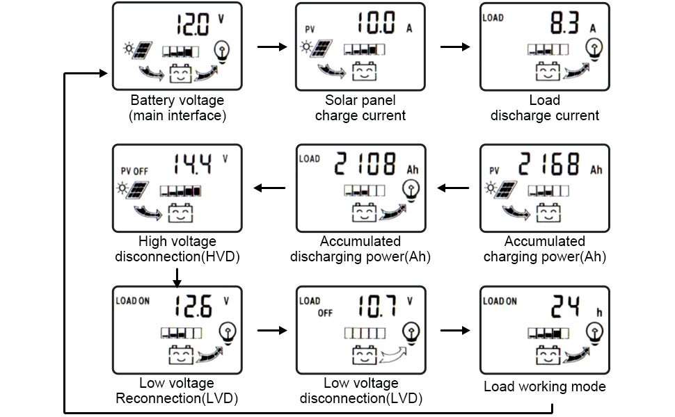
Figure 5: LCD Display Flow
- Battery Voltage (Main Interface): Shows the current battery voltage.
- Solar Panel Charge Current: Displays the current flowing from the solar panel to the battery.
- Load Discharge Current: Shows the current being drawn by the connected load.
- High Voltage Disconnection (HVD): The voltage at which charging stops to prevent overcharging.
- Accumulated Discharging Power (Ah): Total ampere-hours discharged from the battery.
- Accumulated Charging Power (Ah): Total ampere-hours charged into the battery.
- Low Voltage Reconnection (LVD): The voltage at which the load output is re-enabled after low voltage disconnection.
- Low Voltage Disconnection (LVD): The voltage at which the load output is disconnected to protect the battery from over-discharge.
- Load Working Mode: Configurable setting for load operation (e.g., 24 hours, dusk to dawn, timed).
5.2. Setting Parameters
To adjust parameters, press and hold the Menu button until the display flashes. Use the Up/Down buttons to change values and the Menu button to confirm and move to the next setting.
6. Maintenance
Regular maintenance ensures the longevity and optimal performance of your solar charge controller:
- Cleanliness: Keep the controller clean and free from dust and debris. Use a dry cloth to wipe the surface.
- Connections: Periodically check all wiring connections for tightness and corrosion. Loose connections can cause overheating and poor performance.
- Ventilation: Ensure the installation area remains well-ventilated to prevent overheating of the controller.
- Battery Health: Monitor your battery's health and electrolyte levels (for flooded lead-acid batteries) as per the battery manufacturer's recommendations.
7. Troubleshooting
If you encounter issues with your solar charge controller, refer to the following common problems and solutions:
| Problem | Possible Cause | Solution |
|---|---|---|
| No display/No power | Loose battery connection, battery voltage too low, reverse polarity. | Check battery connections, ensure battery voltage is above minimum operating voltage, verify correct polarity. |
| Battery not charging | No solar input, solar panel reverse polarity, open circuit in solar array, controller fault. | Check solar panel connections, verify correct polarity, inspect solar array for damage, contact support if fault persists. |
| Load not working | Load disconnected, low battery voltage (LVD activated), over-current protection, load short circuit. | Check load connections, charge battery, reduce load, check for short circuits in load wiring. |
| Overheating | Poor ventilation, excessive load, high ambient temperature. | Improve ventilation, reduce load, relocate controller to a cooler environment. |
8. Specifications
Detailed technical specifications for the iSunergy MPPT Solar Charge Controller (Model YCX50A):
- Brand: iSunergy
- Model Number: YCX50A
- Current Rating: 50A (This model)
- System Voltage: 12V/24V Auto-sensing
- Display Type: LCD
- Charging Port Type: Dual USB (5V, 2.5A Max)
- Material: Lead (likely referring to compatible battery type, not controller material)
- Package Dimensions: 6.85 x 4.06 x 1.73 inches
- Item Weight: 10.6 ounces
- Manufacturer: iSunergy
- UPC: 732376584685

Figure 6: Product Dimensions
9. Application
The iSunergy MPPT Solar Charge Controller is suitable for a variety of off-grid solar power applications, including but not limited to:
- Residential solar systems
- RV and camper power systems
- Marine applications
- Remote monitoring stations
- Small off-grid cabins

Figure 7: Typical Applications
10. Warranty and Support
For warranty information, technical support, or further assistance, please refer to the official user manual provided with your product or contact iSunergy customer service. A digital version of the user manual can be found here.
For additional product information and support, visit the official iSunergy store on Amazon: iSunergy Store.