
1. Introduction
This manual provides essential instructions for the installation, operation, and maintenance of the Transition Networks SISGM1040-284-LRT Managed Hardened Gigabit Ethernet Switch. The SISGM1040-284-LRT is designed for reliable network connectivity in demanding environments, offering 24 Gbps switching capacity and integrated Device Management System (DMS) software for comprehensive network management. This hardened switch is certified for use in harsh conditions such as factory floors and outdoor enclosures.
2. Product Overview
2.1 Key Features
- Store-and-Forward Architecture with 24 Gbps Switching Bandwidth
- IPv4/IPv6 dual protocols support
- Supports Jumbo frames up to 9K Bytes
- Rapid Ring for fast network recovery
- Radius, TACACS+, User Authentication for enhanced security
- Supports LLDP Protocol for network discovery
- IEEE 1588 v2 PTP for precise time synchronization
- Port Mirroring for network monitoring
- Syslog for event logging
- Static routing capabilities
2.2 Front Panel Layout
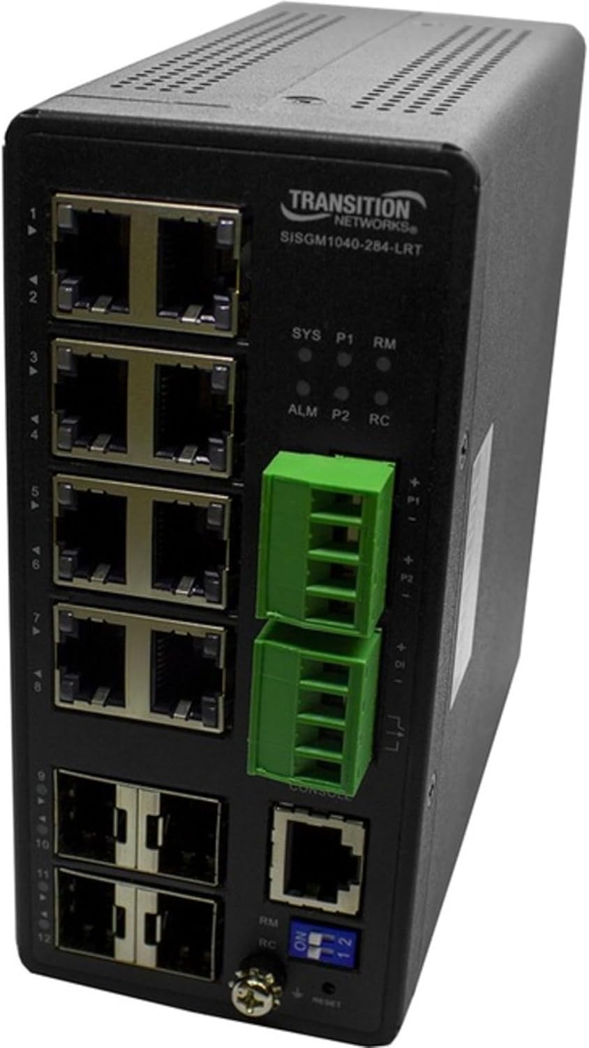
Figure 1: Front Panel of SISGM1040-284-LRT Switch
The image displays the front panel of the Transition Networks SISGM1040-284-LRT switch. On the left side, there are twelve RJ45 Ethernet ports, labeled 1 through 12. Above these ports, the "TRANSITION NETWORKS SISGM1040-284-LRT" model name is visible. To the right of the Ethernet ports, there are LED indicators for system status (SYS), power (P1, P2), alarm (ALM), and remote management (RM, RC). Below these LEDs are two green removable terminal blocks for power input, labeled P1 and P2. Further down, there is a console port (RJ45) and two SFP ports. At the bottom right, a set of blue DIP switches labeled "ON 1 2" and a reset button are present, along with indicators for RM and RC.
3. Setup
3.1 Package Contents
Verify that the following items are included in your package:
- Transition Networks SISGM1040-284-LRT Switch
- Mounting hardware (if applicable)
- Documentation (Quick Start Guide, Warranty Information)
If any items are missing or damaged, please contact your vendor immediately.
3.2 Environmental Considerations
- Ensure adequate ventilation around the switch.
- Avoid placing the switch near heat sources or in direct sunlight.
- Protect the device from moisture and extreme temperatures.
- Mount the switch securely in a stable location, suitable for industrial or outdoor environments as specified.
3.3 Power Connection
- Connect the appropriate power source to the P1 and/or P2 terminal blocks on the front panel. Refer to the specifications for voltage requirements.
- Ensure proper polarity when connecting power wires.
- Verify that the power LED (P1/P2) illuminates after connection.
3.4 Network Connections
- Connect Ethernet cables from your network devices (computers, servers, other switches) to the RJ45 ports (1-12) on the switch.
- For fiber optic connections, insert compatible SFP transceivers into the SFP ports and connect fiber optic cables.
- Observe the link/activity LEDs for each port to confirm successful connection.
3.5 Initial Configuration (Console Access)
- Connect a console cable from your computer to the console port on the switch.
- Use a terminal emulation program (e.g., PuTTY, Tera Term) with the following settings: Baud Rate: 115200, Data Bits: 8, Parity: None, Stop Bits: 1, Flow Control: None.
- Follow the on-screen prompts to configure initial network settings such as IP address, subnet mask, and gateway.
4. Operating Instructions
4.1 LED Indicators
Monitor the front panel LEDs for operational status:
- SYS (System): Indicates overall system status. Green for normal operation.
- P1/P2 (Power): Indicates power supply status for P1 and P2 inputs. Green when power is supplied.
- ALM (Alarm): Indicates an alarm condition. Refer to the management interface for details.
- RM/RC (Remote Management/Control): Indicates status related to remote management or control functions.
- Port LEDs: Indicate link status and activity for each Ethernet or SFP port.
4.2 Device Management System (DMS)
The embedded DMS software provides advanced tools for managing the switch and connected IP devices. Access the DMS via a web browser using the switch's configured IP address or through the console port for command-line interface (CLI) management.
- Web Interface: Open a web browser and enter the switch's IP address. Log in with your credentials.
- CLI: Access via the console port for detailed configuration and monitoring.
Refer to the comprehensive DMS User Guide for detailed instructions on configuring features such as VLANs, QoS, security settings, and static routing.
4.3 DIP Switch Functions
The DIP switches on the front panel (labeled "ON 1 2") may control specific hardware functions or modes. Consult the full product manual for the exact functionality of each switch position.
5. Maintenance
5.1 Cleaning
- Ensure the switch is powered off and disconnected from all cables before cleaning.
- Use a soft, dry cloth to wipe the exterior of the device.
- Do not use liquid or aerosol cleaners, as they may damage the device.
5.2 Firmware Updates
Periodically check the Transition Networks website for firmware updates. Keeping the firmware current ensures optimal performance, security, and access to new features. Follow the instructions provided with the firmware update package carefully.
5.3 Environmental Monitoring
Regularly inspect the installation environment to ensure it remains within the specified operating conditions (temperature, humidity, dust levels) to prolong the life of the switch.
6. Troubleshooting
6.1 No Power
- Verify that the power source is active and correctly connected to the P1/P2 terminal blocks.
- Check the power cables for damage.
- Ensure the power supply meets the switch's voltage requirements.
6.2 No Link on Port
- Ensure the Ethernet or fiber optic cable is securely connected at both ends.
- Verify that the connected device is powered on and functioning correctly.
- Test with a different cable or port to rule out cable or port failure.
- Check the port configuration in the DMS to ensure it is enabled and correctly configured.
6.3 Cannot Access Management Interface
- Confirm the switch's IP address and ensure your computer is on the same subnet.
- Check network connectivity between your computer and the switch.
- Verify firewall settings on your computer or network are not blocking access.
- If using the console port, ensure terminal settings are correct.
6.4 Resetting the Switch
If the switch is unresponsive or requires a factory reset, locate the reset button on the front panel. Use a pointed object (e.g., a paperclip) to press and hold the reset button for approximately 5-10 seconds until the system LEDs indicate a reset sequence. Warning: A factory reset will erase all custom configurations.
7. Specifications
| Feature | Detail |
|---|---|
| Model Number | SISGM1040-284-LRT |
| Brand | Transition Networks |
| Item Weight | 2.3 pounds (1.04 kg) |
| Product Dimensions | 5.9 x 3.4 x 2.1 inches (14.99 x 8.64 x 5.33 cm) |
| Case Material | Metal |
| Interface Type | RJ45, SFP |
| Data Transfer Rate | 24 Gigabits Per Second (Switching Capacity) |
| Number of Ports | 8 (RJ45), 2 (SFP) |
| Manufacturer | Transition Networks, Inc |
| UPC | 648177043477 |
| First Available Date | April 19, 2020 |
| Compatible Devices | Desktop (General network devices) |
8. Warranty and Support
Warranty and support information for the Transition Networks SISGM1040-284-LRT switch is typically provided with the product packaging or available on the official Transition Networks website. Please refer to these resources for details regarding warranty coverage, technical support contacts, and service procedures.
For the most current information, visit the Transition Networks official website.


