1. Introduction
This manual provides detailed instructions for the Ampinvt 6000W/18000W Pure Sine Wave Power Inverter Charger. This device converts 48V DC battery power to 120V/240V AC output, suitable for various off-grid solar applications. It features advanced protection mechanisms and multiple operating modes to ensure reliable power supply.
2. Safety Information
WARNING: Please read all safety instructions carefully before installation and operation. Failure to follow these instructions may result in electric shock, fire, or serious injury.
- Ensure proper grounding of the inverter.
- Do not expose the inverter to rain, snow, spray, or excessive dust.
- Avoid disassembling the unit. Refer servicing to qualified personnel.
- Ensure adequate ventilation around the inverter to prevent overheating.
- Use appropriate wiring and circuit breakers for all connections.
- Keep flammable materials away from the inverter.
3. Product Overview
The Ampinvt Pure Sine Wave Inverter features a robust design with an intuitive LCD display and various connection ports. Below are key components and their descriptions.

Figure 3.1: Front view of the Ampinvt 6000W Pure Sine Wave Inverter Charger, showing the LCD display and control buttons.

Figure 3.2: Detailed front panel showing indicator lights (AC, BAT, INV, FAULT) and working mode settings (AC Input Priority, Battery Priority, ECO Mode, Generator Mode, Unattended Mode).

Figure 3.3: Rear view of the inverter, highlighting the AC fuse, AC input/output terminal block, and AC output sockets.
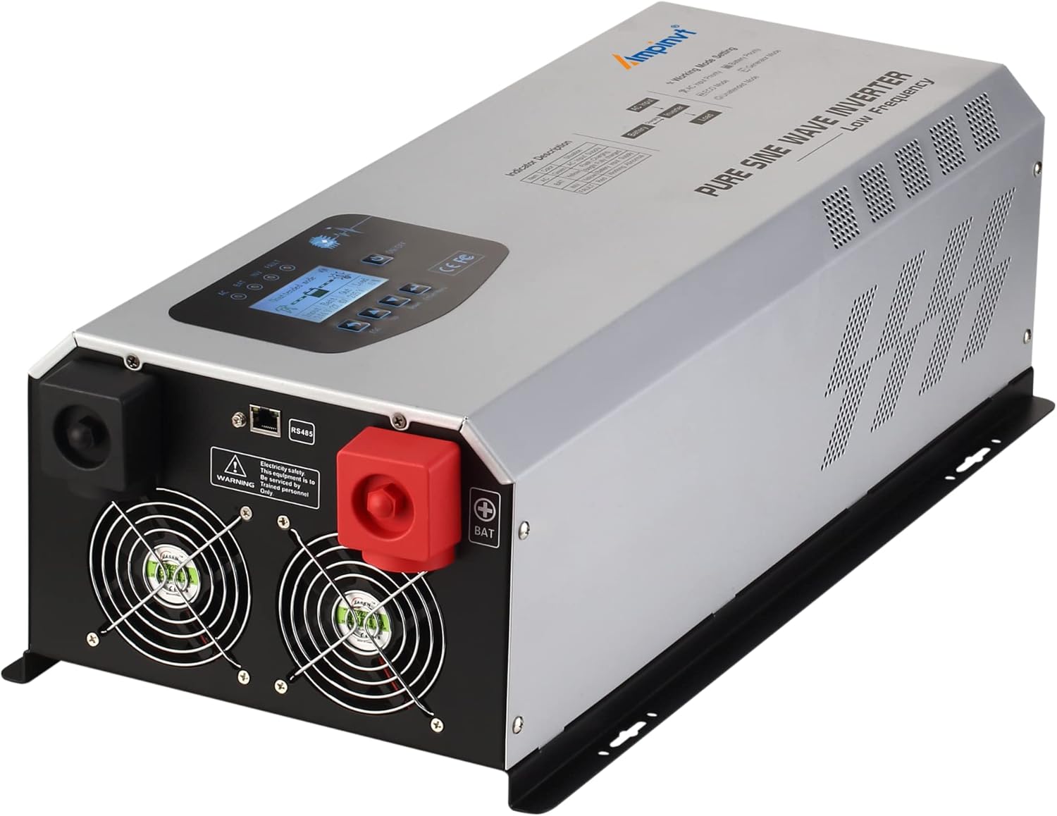
Figure 3.4: Side view of the inverter, showing the positive and negative battery terminals and cooling fans.
4. Setup and Installation
Proper installation is critical for the safe and efficient operation of your Ampinvt inverter. Follow these steps carefully.
4.1 Physical Placement
- Install the inverter in a dry, well-ventilated area, away from direct sunlight and heat sources.
- Ensure sufficient clearance around the unit for proper airflow, especially around the cooling vents.
- Mount the inverter securely on a stable surface.

Figure 4.1: Product dimensions for installation planning. The inverter measures 650mm (length) x 300mm (width) x 185mm (height) and weighs 30.4kg.
4.2 Wiring Connections
All wiring should be performed by a qualified electrician. Ensure all power sources are disconnected before making any connections.
- Battery Connection: Connect the DC battery cables to the inverter's battery terminals. Ensure correct polarity (red to positive, black to negative).
- AC Input Connection: Connect the AC input power source (e.g., grid or generator) to the AC INPUT terminal block.
- AC Output Connection: Connect your AC loads to the AC OUTPUT terminal block or directly to the AC output sockets.
- Grounding: Connect the inverter to an appropriate earth ground.

Figure 4.2: Detailed wiring diagram illustrating connections for AC input (L, N, G), AC output (HOT1, N, HOT2, GND for 120V/240V split phase), and battery terminals.
4.3 Remote Panel Connection (Optional)
The inverter supports an optional remote panel for convenient monitoring and control.

Figure 4.3: The intelligent remote panel connection port (RS485) on the inverter and an example of the remote screen (purchased separately).
4.4 Setup Video Guide
Video 4.1: This video demonstrates the physical overview, battery connection, mains input/output wiring, and basic operation mode settings of the Ampinvt off-grid low frequency inverter with AC charger.
5. Operating Instructions
The inverter features an LCD display for monitoring and configuration, along with several working modes to suit different power requirements.
5.1 LCD Display and Controls
The LCD provides real-time data and allows adjustment of settings. Use the ESC, Up, Down, and Enter/Menu buttons to navigate and configure the inverter.
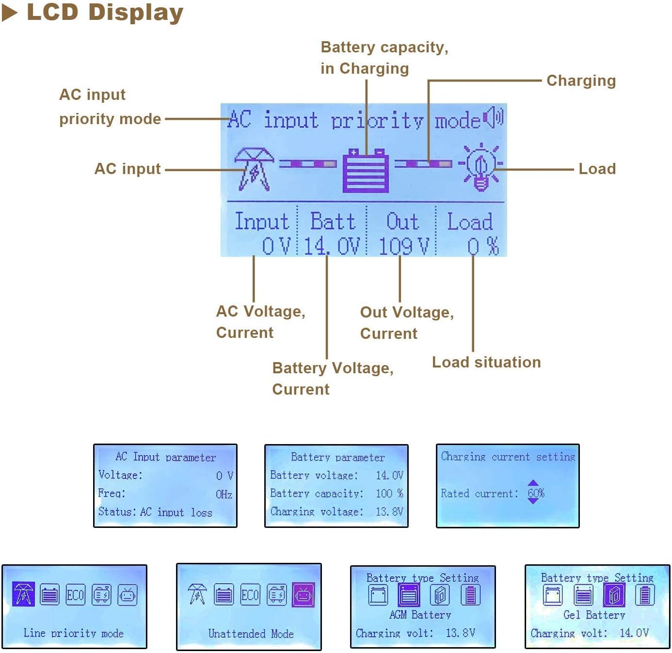
Figure 5.1: The LCD display interface, showing AC input priority mode, battery voltage, output voltage, load status, and options for setting battery type and charging current.

Figure 5.2: Status indicator lights (AC, Battery, Inverter, Fault) and a description of the LCD display button functions (Return, Up, Down, Confirm, Turn On/Off).
5.2 Working Modes
The inverter offers five distinct working modes, configurable via the LCD display:
- AC Input Priority Mode: Prioritizes utility power (110V AC). If utility power fails, the inverter switches to battery power. When utility power returns, it switches back.
- Battery Priority Mode: Prioritizes battery power. If battery voltage drops below a set threshold, it switches to utility power. Once the battery is sufficiently charged, it reverts to battery power.
- ECO Mode: For energy saving. If the load is less than 10%, the inverter enters sleep mode and stops output. It automatically restarts normal inversion when the load exceeds 10%.
- Generator Mode: Designed for use with unstable AC voltage sources, such as generators. The inverter's AVR regulator stabilizes the output voltage.
- Unattended Mode: When battery voltage is low, the inverter enters a standby (power-saving) state. It automatically restores normal output when the battery voltage recovers (e.g., from solar charging), enabling fully automatic operation without supervision.
5.3 Adjustable Settings
- AC Charging Voltage & Current: Adjustable charging voltage (13.4-14.9VDC for 12V systems) and current (0-35A) for various battery types.
- Low Voltage Protection & Recovery: Customizable voltage thresholds for low voltage protection and recovery to prevent battery over-discharge.
- Battery Type Setting: Compatible with Sealed, Gel, AGM, Flooded, and Lithium batteries. Ensure the correct battery type is selected for optimal charging and discharge cycles.
6. Maintenance
Regular maintenance ensures the longevity and optimal performance of your inverter.
- Cleaning: Periodically clean the exterior of the inverter and ensure cooling vents are free from dust and debris. Use a dry cloth.
- Connections: Regularly check all electrical connections (battery, AC input, AC output) for tightness and corrosion. Tighten any loose connections.
- Battery Health: Monitor battery voltage and health according to battery manufacturer guidelines. Ensure proper charging cycles.
- Environment: Maintain the operating environment within specified temperature and humidity ranges.
7. Troubleshooting
This section provides solutions to common issues. For complex problems, contact qualified service personnel.
| Problem | Possible Cause | Solution |
|---|---|---|
| No AC Output | Low battery voltage, overload, short circuit, high temperature. | Check battery charge, reduce load, check for short circuits, allow inverter to cool. |
| Inverter not turning on | Loose battery connections, blown fuse, battery completely discharged. | Check battery connections, replace fuse, charge battery. |
| AC Input not charging battery | AC input voltage out of range, AC input priority mode not selected, charger fault. | Verify AC input voltage, select AC Input Priority mode, contact support if charger fault persists. |
8. Specifications
| Feature | Detail |
|---|---|
| Model Name | Ampinvt 6000W |
| Continuous Power | 6000 Watts |
| Peak Power | 18000 Watts |
| Input Battery Voltage | 48VDC |
| AC Input Voltage Range | 85V-135V |
| AC Output Voltage | 120VAC/240VAC ±3% (battery mode) |
| Output Wave Form | Pure Sine Wave |
| Conversion Efficiency | ≥90% |
| AC Charging Current | 0-35A (adjustable) |
| Protection Features | Over-voltage, overload, low-voltage, high-temperature, short-circuit |
| Dimensions (L x W x H) | 23.8 x 6.7 x 10.2 inches (650 x 300 x 185 mm) |
| Weight | 66 pounds (30.4 kg) |
| Operating Temperature | -25°C to +75°C |
9. Warranty and Support
For warranty information, technical support, or service inquiries, please refer to the contact details provided with your product packaging or visit the official AMPINVT website. Keep your purchase receipt for warranty claims.


