ALAMSCN ALAMSCN
TP4056 Type-C USB 5V 1A 18650 Lithium Battery Charger Module
Instruction Manual
Brand: ALAMSCN
1. Product Overview
The ALAMSCN TP4056 Type-C USB 5V 1A 18650 Lithium Battery Charger Module is a compact and efficient charging board designed for single-cell lithium batteries. It features a Type-C USB input for convenient charging with standard mobile phone chargers and includes dual protection functions for safe operation.

Figure 1: A pack of 12 TP4056 Type-C USB Lithium Battery Charger Modules.
Module Performance Characteristics:
- Input Interface: Type-C USB
- Input Voltage: 4.35V - 6V (recommended 5V)
- Charge Cut-off Voltage: 4.2V +/- 1%
- Maximum Charging Current Output: 1000 mA (1A)
- Battery Overcharge Protection Voltage: 4.28V
- Battery Overcharge Lifting Voltage: 4.00V
- Battery Discharge Protection Voltage: 3.0V
- Battery Discharge Termination Voltage: 3.2V
- Battery Over-current Protection Current: 3A
- Board Size: Approximately 2.5 cm x 1.65 cm

Figure 2: Detailed labeled diagram of the TP4056 module, highlighting key components like the TP4056A processor, 8205A MOSFET, DW01A protection circuit, and indicators.
2. Setup and Installation
Follow these steps to set up your TP4056 charger module:
- Connect Battery: Connect your 18650 lithium battery to the B+ and B- pads on the module. Ensure correct polarity: B+ to battery positive, B- to battery negative.
- Activate Protection Circuit (First Use): When the battery is connected for the first time, there may be no voltage output between OUT+ and OUT-. To activate the protection circuit, connect a 5V power source to the Type-C USB port or the IN+ and IN- pads.
- Output Connection: If using the module for a load, connect your device to the OUT+ and OUT- pads.
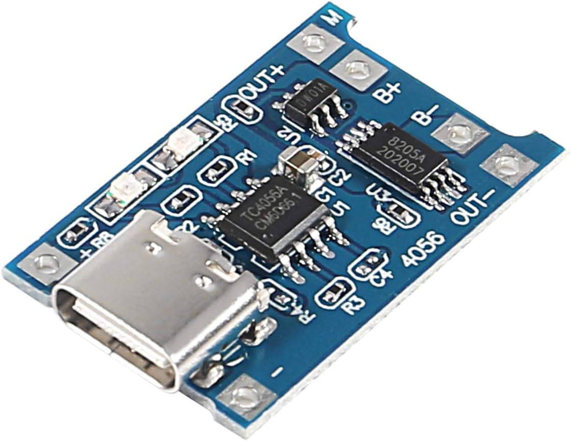
Figure 3: Top view of a single TP4056 module, showing the Type-C USB port and connection pads.
3. Operating Instructions
Once the module is set up, follow these guidelines for operation:
- Charging Input: Insert a Type-C USB cable connected to a 5V power source (e.g., a mobile phone charger) into the module's Type-C USB socket. Alternatively, connect 5V power directly to the IN+ and IN- pads.
- Charger Current Requirement: Ensure your mobile phone charger or power supply can output 1A or more for normal charging operation. Lower current chargers may not charge effectively.
- Charging Indicators:
- When no load is connected, the indicator lights will not be bright.
- During charging, the red light will illuminate.
- When the battery is fully charged, the green light will illuminate.
- Discharge Function: The module provides a two-in-one charging and discharging protection function. When a load is connected to OUT+ and OUT-, the module will supply power from the battery while also protecting it from over-discharge.
4. Maintenance
To ensure the longevity and optimal performance of your TP4056 charger module, consider the following maintenance tips:
- Keep Clean: Periodically clean the module with a soft, dry cloth to remove dust and debris. Avoid using liquids or harsh chemicals.
- Store Properly: When not in use, store the module in a dry, cool environment away from direct sunlight and extreme temperatures.
- Handle with Care: Avoid dropping or subjecting the module to physical shock, as this can damage internal components.
- Inspect Connections: Regularly check all wire connections to ensure they are secure and free from corrosion.
5. Troubleshooting
If you encounter issues with your TP4056 charger module, refer to the following common problems and solutions:
- No Voltage Output (OUT+ / OUT-) on First Connection:
Problem: After connecting the battery for the first time, there is no voltage output from OUT+ and OUT-.
Solution: The protection circuit needs to be activated. Connect a 5V power source to the Type-C USB port or IN+ and IN- pads to initiate charging and activate the circuit.
- Module Not Charging Normally:
Problem: The module does not seem to be charging the battery, or the charging indicator does not behave as expected.
Solution: Ensure your input power source (e.g., mobile phone charger) can provide at least 1A of current. Chargers with lower current output may not be sufficient for normal operation.
- Protection Circuit Needs Reactivation After Short Circuit:
Problem: If the battery connected to B+ B- was short-circuited and then reconnected, the module might not function.
Solution: The protection circuit needs to be reactivated. Connect a 5V power source to the Type-C USB port or IN+ and IN- pads to charge and reset the circuit.
6. Specifications
| Feature | Specification |
|---|---|
| Input Interface | Type-C USB |
| Input Voltage | 4.35V - 6V (Recommended 5V) |
| Charge Cut-off Voltage | 4.2V ± 1% |
| Max Charging Current Output | 1000 mA (1A) |
| Battery Overcharge Protection Voltage | 4.28V |
| Battery Overcharge Lifting Voltage | 4.00V |
| Battery Discharge Protection Voltage | 3.0V |
| Battery Discharge Termination Voltage | 3.2V |
| Battery Over-current Protection Current | 3A |
| Board Dimensions (L x W) | Approx. 2.5 cm x 1.65 cm (0.98 x 0.65 inches) |
| Item Weight | Approx. 20 grams (0.705 ounces) |
| Package Dimensions | 3.66 x 2.95 x 0.63 inches |
7. Warranty and Support
Information regarding product warranty and direct customer support is not provided within this instruction manual. For warranty details, technical assistance, or further inquiries, please refer to the product packaging or contact the manufacturer, ALAMSCN, directly through their official website or authorized retailers.