1. Introduction
This manual provides comprehensive instructions for the installation, operation, maintenance, and troubleshooting of the IBASE Technology MI953F ITX Motherboard. Designed for industrial and embedded applications, the MI953F supports Intel Core i7/i5 processors with a Socket G interface and features the Intel QM57 PCH. It offers robust connectivity including multiple GbE LAN ports, SATA, COM, and various expansion slots.
2. Safety Information
Please read and follow all safety instructions carefully to prevent damage to the motherboard or injury to yourself. Always disconnect power before handling components. Wear an anti-static wrist strap when installing or removing components to prevent electrostatic discharge (ESD) damage. Do not expose the motherboard to moisture or extreme temperatures. Ensure proper ventilation when the system is in operation.
3. Package Contents
Verify that all items are present in the package. If any item is missing or damaged, contact your vendor immediately.
- IBASE MI953F ITX Motherboard
- SATA Data Cables (quantity may vary)
- I/O Shield
- Driver CD/USB (may not be included with all packages, drivers available online)
- Quick Installation Guide (this document serves as a detailed manual)
4. Product Overview
The IBASE MI953F is a compact Mini-ITX motherboard designed for high-performance embedded applications. It supports Intel Core i7/i5 processors with a Socket G form factor and utilizes the Intel QM57 Platform Controller Hub (PCH). Key features include dual Gigabit Ethernet LAN ports (Intel 82577LM and 82574L), VGA output, four SATA ports, four COM ports, and various expansion options such as PCI, PCI-E(1x), and Mini PCI-E slots.
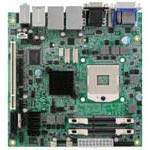
Figure 4.1: Top-down view of the IBASE MI953F ITX Motherboard, showing various components and connectors.
4.1. Key Components and Connectors
- CPU Socket G: For Intel Core i7/i5 processors.
- Intel QM57 PCH: Provides chipset functionalities.
- DIMM Slots: Two slots for DDR3 SO-DIMM memory modules.
- SATA Ports: Four ports for connecting storage devices.
- LAN Ports: Two Gigabit Ethernet ports (82577LM and 82574L).
- VGA Port: For video output.
- COM Ports: Four serial communication ports.
- Expansion Slots: One PCI, one PCI-E(1x), and one Mini PCI-E slot.
- USB Ports: Multiple USB 2.0 ports (internal headers and external).
5. Setup and Installation
5.1. CPU Installation
- Carefully open the CPU socket lever.
- Align the CPU with the socket, ensuring the notches match. Do not force the CPU into the socket.
- Gently place the CPU into the socket.
- Close the socket lever to secure the CPU.
- Apply thermal paste to the CPU and install the CPU cooler according to its instructions.
5.2. Memory (RAM) Installation
- Locate the two DDR3 SO-DIMM slots.
- Open the clips at both ends of the DIMM slot.
- Align the notch on the memory module with the notch in the DIMM slot.
- Insert the module firmly into the slot until the clips snap into place.
5.3. Storage Device Installation
Connect SATA storage devices (HDDs/SSDs) to the SATA ports on the motherboard using SATA data cables. Ensure the power cable from your power supply is also connected to the storage device.
5.4. Peripheral Connections
- Power: Connect the ATX power connector from your power supply to the motherboard.
- Display: Connect your monitor to the VGA port.
- Network: Connect Ethernet cables to the GbE LAN ports.
- USB: Connect USB devices to the external USB ports or internal headers.
- Expansion Cards: Install PCI, PCI-E, or Mini PCI-E cards into their respective slots if required.
6. Operating Instructions
6.1. Initial Power On
After all components are installed and connected, connect the power cord to your power supply and press the power button on your system chassis. The system should initiate the boot process.
6.2. BIOS/UEFI Setup
To enter the BIOS/UEFI setup utility, press the DEL or F2 key repeatedly during the initial boot sequence. The BIOS allows you to configure system settings, boot order, and monitor hardware status. Refer to the IBASE website for detailed BIOS documentation specific to your firmware version.
6.3. Driver Installation
After installing your operating system, install the necessary drivers for the motherboard components. These typically include chipset drivers, graphics drivers, LAN drivers, and audio drivers. Drivers can usually be found on the IBASE official website under the MI953F product page.
7. Maintenance
7.1. Cleaning
Regularly clean dust from the motherboard and system components using compressed air. Ensure the system is powered off and unplugged before cleaning. Avoid using liquid cleaners directly on components.
7.2. Firmware Updates
Periodically check the IBASE website for BIOS/UEFI firmware updates. Firmware updates can improve system stability, performance, and compatibility. Follow the update instructions provided by IBASE carefully to avoid damaging the motherboard.
8. Troubleshooting
| Problem | Possible Cause | Solution |
|---|---|---|
| System does not power on | Loose power connections, faulty power supply, incorrect front panel wiring. | Check all power cables. Verify front panel power switch connection. Test with a known good power supply. |
| No display output | Monitor not connected, faulty RAM, incorrect display output selected, CPU not seated correctly. | Ensure monitor is connected and powered on. Reseat RAM modules. Check display cable. Reseat CPU. |
| Operating system fails to boot | Incorrect boot order, corrupted OS, faulty storage device. | Check BIOS boot order. Reinstall OS. Test storage device. |
| Network connectivity issues | Loose Ethernet cable, missing LAN drivers, incorrect network settings. | Verify Ethernet cable connection. Install/update LAN drivers. Check OS network settings. |
9. Specifications
- Brand: IBASE
- Model: MI953F
- Chipset Type: Intel QM57 PCH
- CPU Model Support: Intel Core i7, Core i5 (Socket G)
- Memory Slots Available: 2 (DDR3 SO-DIMM)
- Graphics Card Interface: PCI Express (1x)
- System Bus Standard Supported: SATA 3
- S/PDIF Connector Type: Optical
- LAN: 2x Gigabit Ethernet (Intel 82577LM, 82574L)
- Video Output: VGA
- SATA Ports: 4
- COM Ports: 4
- Expansion Slots: 1x PCI, 1x PCI-E(1x), 1x Mini PCI-E
- Manufacturer: IBASE Technology
- UPC: 091128536106
- ASIN: B08DYCBWB1
10. Warranty and Support
The IBASE MI953F Motherboard is covered by a manufacturer's warranty. For specific warranty terms and conditions, please refer to the warranty card included with your product or visit the official IBASE Technology website. For technical support, driver downloads, and further assistance, please visit the IBASE Technology support portal or contact their customer service department.
IBASE Technology Official Website: www.ibase.com.tw