1. Introduction
The GVDA GD128 SMART Digital Multimeter is a professional testing instrument designed for accurate and reliable measurements. It is an ideal choice for professional electricians, engineers, electronics enthusiasts, and for general household use. This manual provides detailed instructions on the safe and effective operation of your GD128 multimeter.
Key capabilities include:
- AC and DC Voltage Measurement
- AC and DC Current Measurement
- Resistance Measurement
- Capacitance Measurement
- Continuity Measurement
- Diode Measurement
- NCV (Non-Contact Voltage) Measurement
- True RMS for accurate readings of non-sinusoidal signals
- Large VA color HD LCD screen with 9999 counts display
- Auto and Manual Ranging
- Flashlight and Input Connector LED Indication

Figure 1.1: GVDA GD128 Digital Multimeter with test probes.
2. Safety Information
WARNING: To avoid electrical shock or personal injury, please read and understand all instructions and safety information before using this multimeter.
- Always ensure the multimeter is in the correct function and range before making measurements.
- Do not exceed the maximum input values for any range.
- Use caution when working with voltages above 30V AC RMS, 42V peak, or 60V DC. These voltages pose a shock hazard.
- Inspect test leads for damaged insulation or exposed metal before use. Replace if damaged.
- Do not operate the multimeter if it appears damaged or if it is not operating properly.
- Always disconnect power to the circuit and discharge all high-voltage capacitors before testing resistance, continuity, diodes, or capacitance.
- Ensure the battery cover is securely closed before operation.
- This device meets safety standards EN61010-1,-2-030, EN61010-2-033, EN61326-1 CAT III 1000V, CAT IV 600V.
3. Product Overview and Components
Familiarize yourself with the different parts of your GVDA GD128 Digital Multimeter.

Figure 3.1: Front and side view of the GD128 Multimeter with labeled components.
- NCV Sensor area
- Power key
- Flashlight key
- Warning indicator
- Flashlight
- Input jack indicator
- Jack other than current and NCV
- COM jack (Common)
- mA (<600mA) jack
- 10A jack
- Auto power off key
- Function key
- Display

Figure 3.2: Rear view of the GD128 Multimeter highlighting the integrated LED flashlight.
4. Setup
4.1 Battery Installation
The GVDA GD128 Multimeter requires 3 x 1.5V AAA batteries (not included) for operation.
- Ensure the multimeter is powered off.
- Locate the battery compartment on the back of the device.
- Use a screwdriver to open the battery compartment cover.
- Insert 3 AAA batteries, observing the correct polarity (+ and -) as indicated inside the compartment.
- Replace the battery compartment cover and secure it with the screw.

Figure 4.1: Battery compartment for 3 AAA batteries.
4.2 Connecting Test Leads
Connect the test leads to the appropriate input jacks for the desired measurement function. Always connect the black test lead to the COM (Common) jack. Connect the red test lead to the jack corresponding to the measurement type (e.g., VΩHz for voltage/resistance/frequency, mA for milliampere current, 10A for ampere current).
5. Operating Instructions
The GD128 features both auto-ranging and manual-ranging capabilities. The "SMART" function automatically identifies AC/DC voltage, resistance, and continuity.
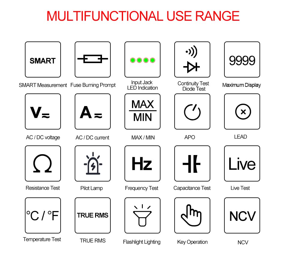
Figure 5.1: Multifunctional Use Range icons.
5.1 Power On/Off
Press the Power key (2) to turn the multimeter on or off.
5.2 Function Selection
The multimeter typically starts in SMART mode. Press the FUNC (Function) key (12) or SEL key to cycle through different measurement modes within a category (e.g., AC/DC voltage, resistance/continuity/diode).
5.3 Common Measurement Functions
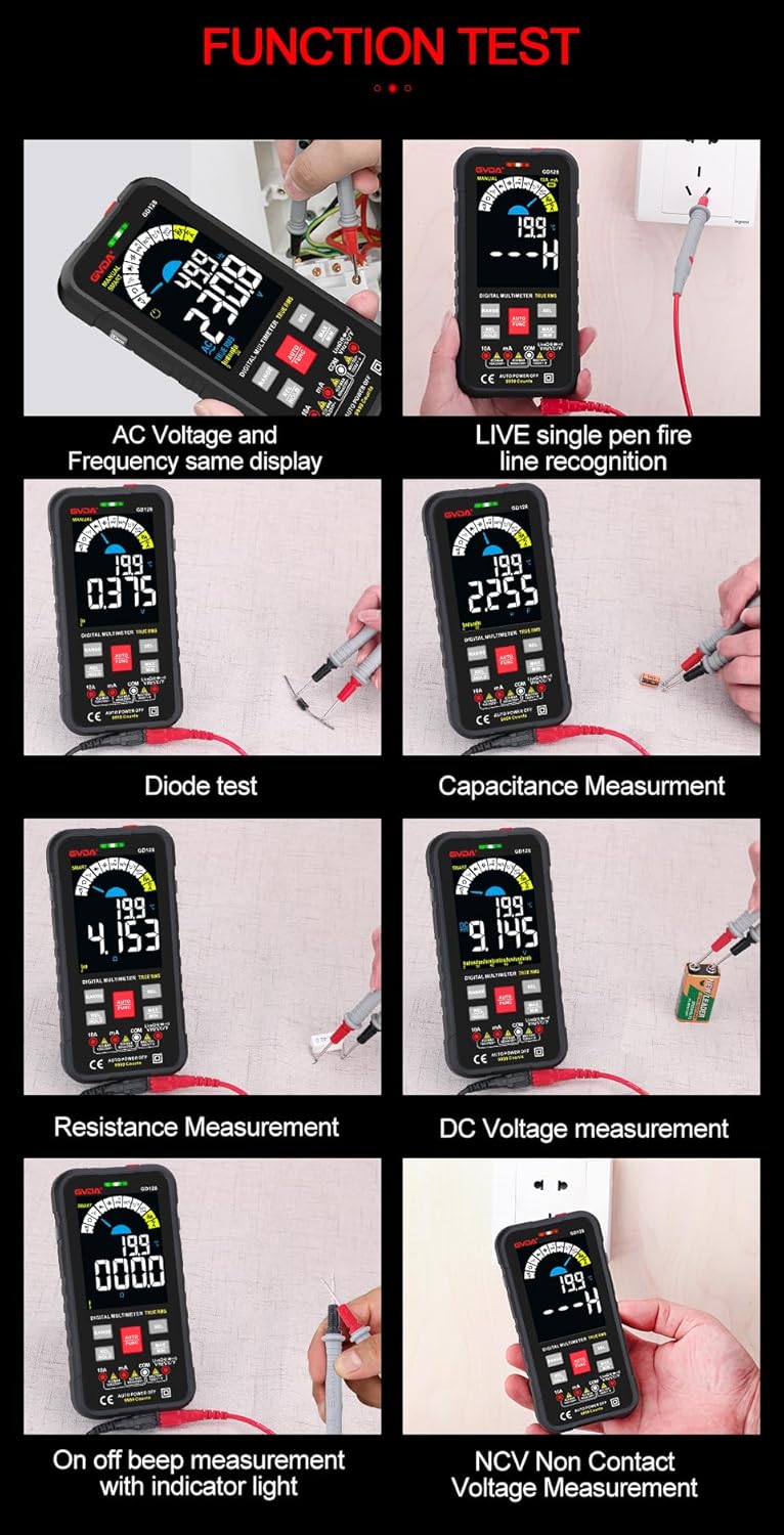
Figure 5.2: Examples of various function tests.
5.3.1 Voltage Measurement (AC/DC)
- Connect the black test lead to the COM jack and the red test lead to the VΩHz jack.
- Select the appropriate AC (~) or DC (---) voltage mode.
- Connect the test leads in parallel to the circuit or component to be measured.
- The display will show the voltage reading.
5.3.2 Current Measurement (AC/DC)
- Connect the black test lead to the COM jack.
- For current up to 600mA, connect the red test lead to the mA jack. For current up to 10A, connect the red test lead to the 10A jack.
- Select the appropriate AC (~) or DC (---) current mode.
- Connect the multimeter in series with the circuit to be measured.
- The display will show the current reading.
5.3.3 Resistance Measurement (Ω)
- Connect the black test lead to the COM jack and the red test lead to the VΩHz jack.
- Select the Resistance (Ω) mode.
- Ensure the circuit is de-energized before measuring resistance.
- Connect the test leads across the component to be measured.
- The display will show the resistance reading.
5.3.4 Capacitance Measurement (F)
- Connect the black test lead to the COM jack and the red test lead to the VΩHz jack.
- Select the Capacitance (F) mode.
- Ensure the capacitor is fully discharged before measurement to avoid damage to the multimeter.
- Connect the test leads across the capacitor terminals.
- The display will show the capacitance reading.
5.3.5 Continuity Test (Ω)
- Connect the black test lead to the COM jack and the red test lead to the VΩHz jack.
- Select the Continuity mode.
- Touch the test leads to the points you want to check for continuity. A continuous beep indicates a complete circuit.
5.3.6 Diode Test (→|)
- Connect the black test lead to the COM jack and the red test lead to the VΩHz jack.
- Select the Diode Test mode.
- Connect the red test lead to the anode and the black test lead to the cathode of the diode. The display will show the forward voltage drop. Reverse the leads; an open circuit (OL) reading indicates a good diode.
5.3.7 NCV (Non-Contact Voltage) Measurement
- Select the NCV mode.
- Move the NCV sensor area (1) near the conductor. The multimeter will beep and the warning indicator (4) will light up with increasing frequency as it detects AC voltage.
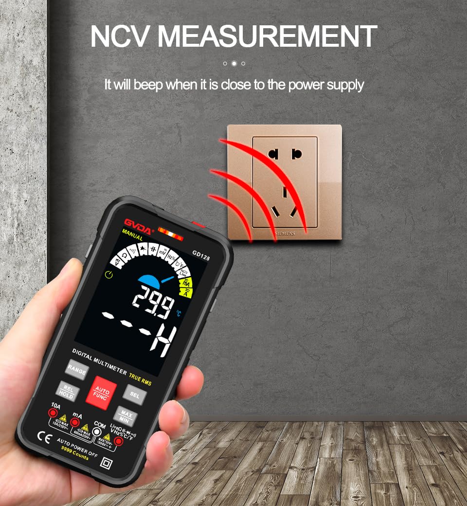
Figure 5.3: NCV (Non-Contact Voltage) measurement in progress.
5.3.8 Other Functions
- True RMS: Provides accurate readings for both sinusoidal and non-sinusoidal AC waveforms.
- MAX/MIN/AVG: Press the MAX/MIN key to record maximum, minimum, and average readings.
- REL (Relative Measurement): Press the REL/HOLD key briefly to set the current reading as a reference for subsequent measurements.
- Data Hold: Press the REL/HOLD key briefly to freeze the current reading on the display.
- Flashlight: Press the Flashlight key (3) to turn the built-in flashlight on/off.
- Auto Power Off (APO): The multimeter will automatically power off after a period of inactivity to save battery life.
6. Applications
The GVDA GD128 Digital Multimeter is versatile and suitable for a wide range of applications, including but not limited to:

Figure 6.1: Diverse applications of the GD128 Multimeter.
- Electronic beginners and hobbyists
- Electronic circuit installation and testing
- Electronic maintenance and repair
- Electromechanical maintenance
- Vehicle inspection and automotive electrical work
- Maintenance of household appliances
- General electrical troubleshooting
7. Specifications
Detailed technical specifications for the GVDA GD128 Digital Multimeter:
| Feature | Range | Precision |
|---|---|---|
| DC Voltage | 99.99mV/999.9mV; 9.999V/99.9V/1000V | ±(0.5%+3) |
| AC Voltage | 99.9mV/999.9/mV; 9.999V/99.9V/750V | ±(0.8%+3) |
| DC Current | 9.999mA/99.99mA/999.9mA; 9.99A | ±(0.8%+3) for mA, ±(1.2%+3) for A |
| AC Current | 9.999mA/99.99mA/999.9mA; 9.99A | ±(1.0%+3) for mA, ±(1.5%+3) for A |
| Resistance | 99.99/999.9 ohms/9.999k/99.99k/999.9kohm; 9.999 m/99.99 m ohms | ±(0.8%+3) for kΩ, ±(1.2%+3) for MΩ |
| Capacitance | 9.999/99.99/999.9nF/9.999/99.99/999.9uF; 9.999mF/99.99mF | ±(4.0%+3) for nF/uF, ±(5.0%+5) for mF |
| Frequency | 99.99/999.9/9.999k/99.99k/999.9kHz/9.999mHz | ±(1.0%+3) |
| Duty Cycle | 0.1%-99.99% | ±(1.0%+2) |
| Temperature | -40~1000°C; -40-1832°F | ±2°C |
| Display Count | 9999 counts | |
| Display Type | VA color screen | |
| Sampling Rate | Approx. 3 times per second | |
| Over Range Display | "OL" | |
| Low Voltage Indication | Low battery indication | |
| Power Supply | 3 x 1.5V AAA batteries (not included) | |
| Product Weight | Approx. 230g | |
| Product Size | 83x23x165mm | |
| Safety Rating | EN61010-1,-2-030 EN61010-2-033, EN61326-1 CAT III 1000 V CAT IV 600 V |
8. Maintenance
Proper maintenance ensures the longevity and accuracy of your multimeter.
- Cleaning: Wipe the case with a damp cloth and mild detergent. Do not use abrasives or solvents.
- Battery Replacement: Replace batteries promptly when the low battery indicator appears to ensure accurate readings.
- Fuse Replacement: If the current measurement function fails, the fuse may be blown. Refer to the warning label inside the battery compartment for fuse specifications (e.g., F600mA/250V, F10A/250V). Ensure the multimeter is off and test leads are disconnected before replacing fuses.
- Storage: If the multimeter is not used for a long period, remove the batteries to prevent leakage. Store in a cool, dry place away from direct sunlight.
9. Troubleshooting
If you encounter issues with your GVDA GD128 Multimeter, try the following:
- No Display/Power On: Check battery installation and ensure batteries are not depleted. Replace if necessary.
- Incorrect Readings: Verify test lead connections, ensure the correct function and range are selected, and check if the circuit is de-energized for resistance/continuity/capacitance tests.
- "OL" Display: Indicates an over-range condition or an open circuit (e.g., when measuring resistance on an open wire).
- No Continuity Beep: Check if the circuit is truly continuous. If not, the circuit is open.
- Fuse Blown Warning: If the current measurement function is not working, the fuse might be blown. Replace the fuse as per maintenance instructions.
For persistent issues, contact customer support.
10. Warranty and Support
Your GVDA GD128 Digital Multimeter comes with a 30-day warranty for system failures or factory problems. Please retain your proof of purchase for warranty claims.
For technical support, warranty claims, or further assistance, please refer to the contact information provided with your product packaging or visit the official GVDA website.
11. Package Contents
Upon opening your GVDA GD128 Digital Multimeter package, you should find the following items:

Figure 11.1: Contents included in the GD128 Multimeter package.
- 1 x GVDA GD128 Digital Multimeter
- 1 x Test Lead Set (Original pen cable)
- 1 x Cloth Bag
- 1 x Thermocouple Probe
- 1 x User Manual
- 1 x Gift Box (Packaging)


