1. Introduction
This manual provides detailed instructions for the safe and efficient use of your Ymiko XL6009 DC to DC Boost Converter Module. This module is designed to step up DC voltage from 3.0-30V to an adjustable output of 5-35V, making it suitable for various applications such as powering laptops or regulating voltage for solar panels.
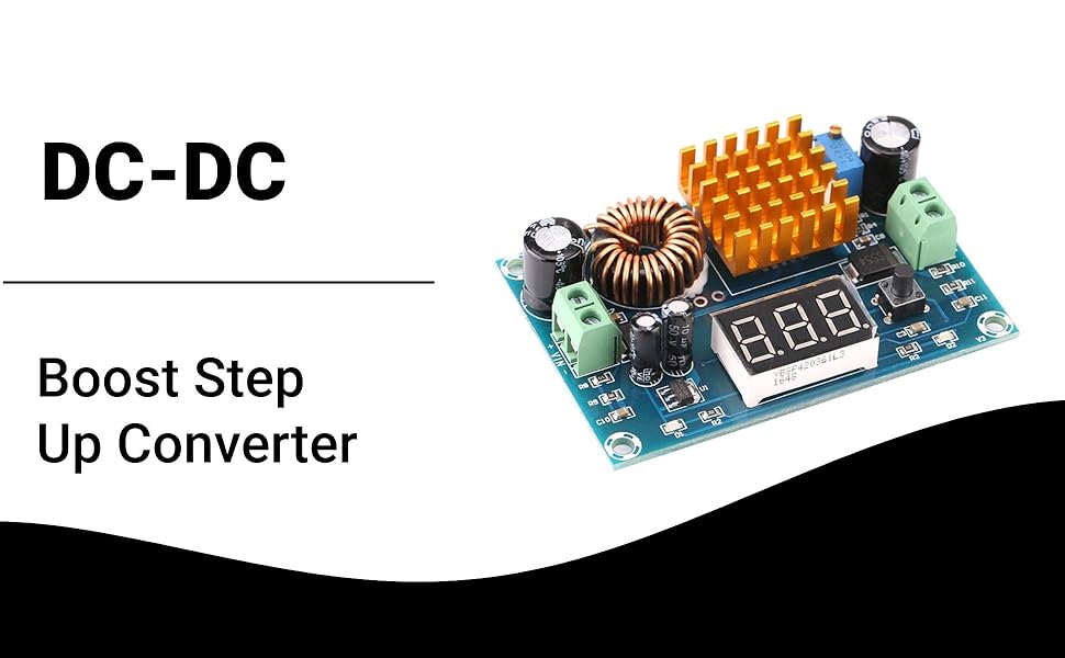
Image: Ymiko XL6009 Boost Converter Module in an application setup, demonstrating its use with solar panels and laptops.
2. Safety Information
Please read and understand all safety warnings before operating the module. Failure to follow these instructions may result in electric shock, fire, or serious injury.
- Always ensure correct polarity when connecting input and output power. Incorrect connections can damage the module and connected devices.
- Do not exceed the maximum input voltage of 30V or the maximum output voltage of 35V.
- Do not exceed the maximum output current. Refer to specifications for current limits.
- Handle the module with care to prevent electrostatic discharge (ESD), which can damage sensitive electronic components.
- Disconnect all power sources before making any connections, disconnections, or adjustments to the module.
- Keep the module away from moisture, dust, and extreme temperatures.
- Ensure adequate ventilation around the module, especially the heat sink, to prevent overheating.
3. Product Overview
3.1 Features
- DC to DC step-up power supply module.
- Input voltage range: 3.0V to 30V.
- Adjustable output voltage range: 5V to 35V.
- Equipped with screw terminals for convenient wire connection and disconnection.
- Integrated heat sink for efficient heat dissipation.
- Onboard digital display for real-time voltage monitoring (input or output).
3.2 Components

Image: Top-down view of the Ymiko XL6009 module, highlighting the input/output terminals, digital display, adjustment potentiometer, and heat sink.
- VIN+ / VIN- Terminals: Input voltage connection points.
- VOUT+ / VOUT- Terminals: Output voltage connection points.
- Digital Display: 3-digit LED display for showing input or output voltage.
- Mode Button: Toggles the digital display between input voltage and output voltage.
- Adjustment Potentiometer (ADJ): Blue multi-turn potentiometer used to adjust the output voltage.
- Heat Sink: Gold-colored finned component for thermal management.
- Inductor: Large copper coil component.
Video: A demonstration of the Ymiko Boost Converter Module, showing its physical appearance and various angles.
4. Setup
Follow these steps to correctly set up your boost converter module:
- Prepare Wiring: Ensure you have appropriate wires for your input power source and your load. Strip a small amount of insulation from the ends of the wires.
- Connect Input Power:
- Loosen the screws on the green input terminal block labeled "VIN+".
- Insert the positive (+) wire from your DC power source (e.g., battery, power supply) into the "VIN+" terminal.
- Tighten the screw to secure the wire.
- Repeat for the negative (-) wire, connecting it to the "VIN-" terminal.
- Connect Output Load:
- Loosen the screws on the green output terminal block labeled "VOUT+".
- Insert the positive (+) wire for your load (e.g., laptop, other electronic equipment) into the "VOUT+" terminal.
- Tighten the screw to secure the wire.
- Repeat for the negative (-) wire, connecting it to the "VOUT-" terminal.
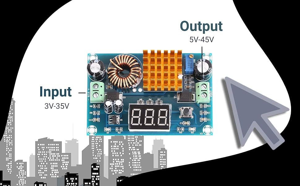
Image: Diagram illustrating the input (3V-35V) and output (5V-45V) terminals on the Ymiko XL6009 module.

Image: The boost converter module connected to an external DC power supply, demonstrating typical wiring for testing or operation.
5. Operating Instructions
Once the module is wired, you can proceed with operation:
- Power On: Apply power to your input source. The digital display on the module should illuminate, showing the current voltage (default is often input voltage).
- Check Voltage Display: Press the small black button next to the digital display to toggle between showing the input voltage (IN) and the output voltage (OUT). It is recommended to monitor the output voltage during adjustment.
- Adjust Output Voltage:
- Using a small flat-head screwdriver, carefully turn the blue potentiometer (labeled "ADJ") located near the output terminals.
- Turn clockwise to increase the output voltage.
- Turn counter-clockwise to decrease the output voltage.
- Adjust until the desired output voltage (between 5V and 35V) is displayed.
- Note: The potentiometer may require multiple turns to see a significant change in voltage. Adjust slowly and observe the display.
- Verify Operation: Once the desired output voltage is set, ensure your connected load is functioning correctly.
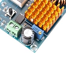
Image: A close-up view of the blue adjustment potentiometer (ADJ) used for setting the output voltage.
6. Maintenance
To ensure the longevity and optimal performance of your Ymiko XL6009 Boost Converter Module, follow these maintenance guidelines:
- Cleaning: Keep the module clean and free from dust and debris. Use a soft, dry brush or compressed air to gently clean the circuit board and heat sink. Do not use liquids.
- Ventilation: Ensure the module is operated in a well-ventilated area. Do not obstruct the heat sink, as proper airflow is crucial for heat dissipation.
- Storage: When not in use, store the module in a dry, cool environment, away from direct sunlight and extreme temperatures.
- Inspection: Periodically inspect the wiring connections to ensure they are secure and free from corrosion or damage.
7. Troubleshooting
If you encounter issues with your Ymiko XL6009 module, refer to the following troubleshooting steps:
| Problem | Possible Cause | Solution |
|---|---|---|
| No display or power output. | No input power, incorrect input polarity, or faulty connection. | Check input power source. Verify input wiring polarity (VIN+ to positive, VIN- to negative). Ensure all connections are secure. |
| Output voltage is not adjustable. | Input voltage too low for desired output, potentiometer malfunction, or module fault. | Ensure input voltage is within 3.0-30V and sufficient for the target output. Turn the potentiometer multiple times to confirm it's not at an extreme end. If the issue persists, the module may be faulty. |
| Module overheats. | Excessive load current, insufficient ventilation, or short circuit. | Reduce the load current. Ensure the module has adequate airflow around the heat sink. Check for any short circuits in the output wiring. |
| Output voltage is unstable. | Unstable input power, loose connections, or faulty components. | Ensure the input power source is stable. Check all wiring connections for tightness. |
8. Specifications
| Parameter | Value |
|---|---|
| Brand | Ymiko |
| Model Number | Ymikouqv9ftz5rp (XL6009) |
| Input Voltage | 3.0V - 30V DC |
| Output Voltage | 5V - 35V DC (Adjustable) |
| Dimensions (L x W x H) | 72mm x 48mm x 16mm |
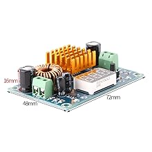
Image: The Ymiko XL6009 module with its approximate dimensions: 72mm length, 48mm width, and 16mm height.
9. Warranty and Support
Ymiko is committed to providing high-quality products. If you experience any quality issues with your Boost Converter Module, please do not hesitate to contact Ymiko customer service. We aim to provide friendly and helpful support.
For specific warranty details and contact information, please refer to your purchase documentation or visit the official Ymiko website.
Online Resources:
- Ymiko Store on Amazon: Visit the Ymiko Store


