1. Introduction
The Fdit TAG-101 Audio Signal Generator is a versatile low-frequency signal source designed for various applications including production lines, hobbyist projects, and maintenance tasks. It is capable of generating sine and square wave signals within a frequency range of 10 Hz to 1 MHz with low distortion. This manual provides essential information for the safe and effective operation of your device.
2. Safety Instructions
- Always connect the device to a grounded power outlet with the correct voltage (AC 220V, 50/60Hz).
- Do not operate the device in wet or damp conditions.
- Avoid exposing the device to extreme temperatures or direct sunlight.
- Do not open the casing of the device. Refer all servicing to qualified personnel.
- Ensure proper ventilation around the unit during operation.
- Disconnect the power cable before cleaning or when the device is not in use for extended periods.
3. Package Contents
Please check the package for the following items:
- 1 x Fdit TAG-101 Audio Signal Generator
- 1 x Instruction Manual (this document)
- 1 x Power Cable

Figure 3.1: Included Power Cable
4. Product Overview
The Fdit TAG-101 features a user-friendly front panel with controls for frequency, amplitude, waveform selection, and output attenuation.

Figure 4.1: Front Panel Layout

Figure 4.2: Key Features of the Signal Generator
4.1. Controls and Connectors
- FREQUENCY Dial: Adjusts the output frequency within the selected range.
- RANGE (Hz) Buttons: Selects the frequency multiplication range (X1, X10, X100, X1K, X10K) to achieve frequencies from 10Hz to 1MHz.
- ATTENUATOR (dB) Knob: Provides step-wise attenuation of the output signal (0dB, -10dB, -20dB, -30dB, -40dB, -50dB).
- AMPLITUDE Knob: Fine-tunes the output signal amplitude.
- WAVE FORM Switches: Selects between Sine wave and Square wave output.
- POWER Switch: Turns the device ON or OFF.
- EXT SYNC Input: BNC connector for external synchronization.
- OUTPUT (600Ω) Connector: BNC connector for signal output.
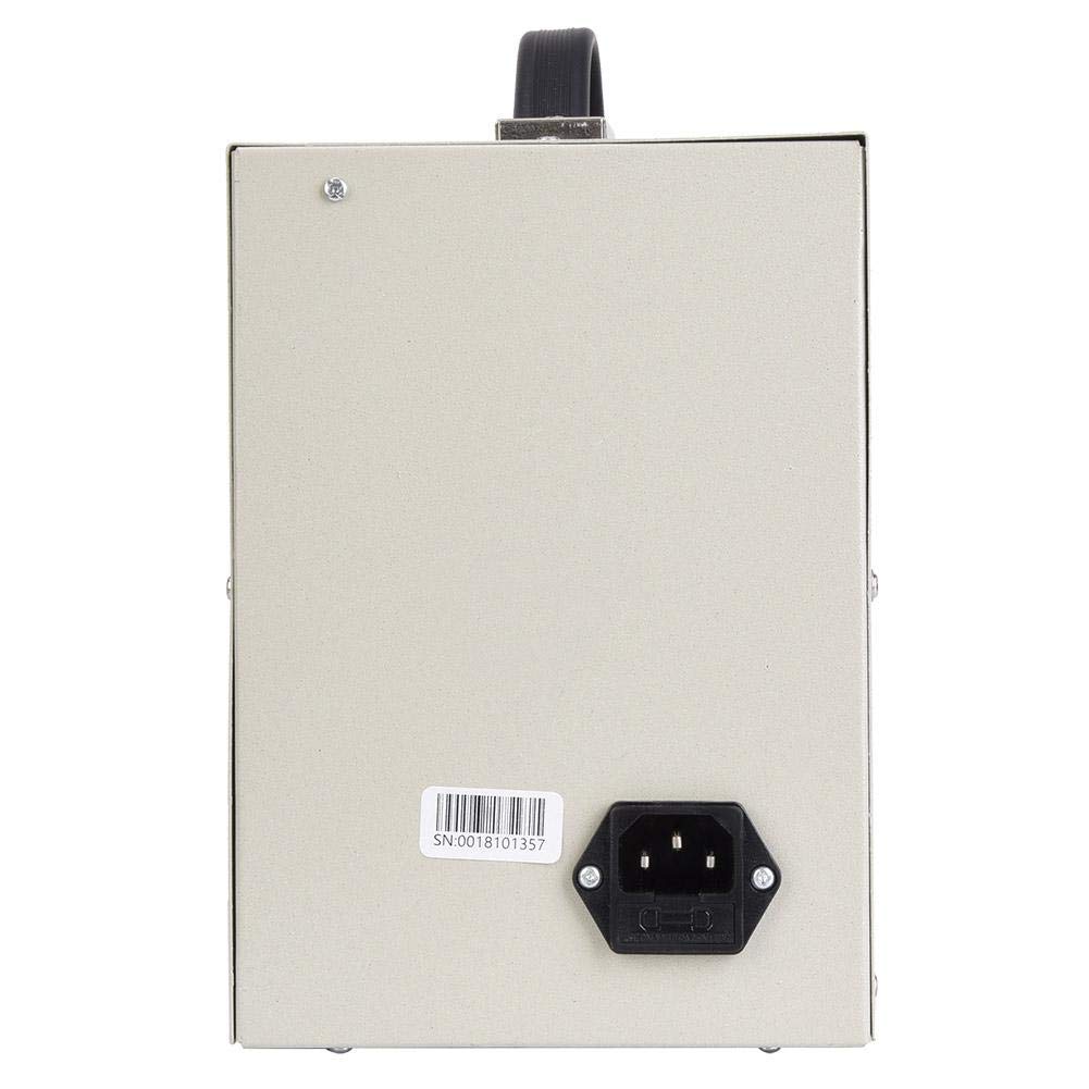
Figure 4.3: Rear Panel with Power Input
5. Setup
- Unpack the Device: Carefully remove the signal generator and all accessories from its packaging.
- Placement: Place the signal generator on a stable, flat surface with adequate ventilation. Ensure it is away from direct heat sources, moisture, and strong electromagnetic fields.
- Connect Power: Insert the provided power cable into the power input socket on the rear panel of the device. Plug the other end into a suitable AC 220V (50/60Hz) grounded power outlet.
- Initial Inspection: Before powering on, visually inspect the device for any signs of damage.
6. Operating Instructions
6.1. Powering On/Off
- To power on the device, press the POWER switch to the 'ON' position.
- To power off, press the POWER switch to the 'OFF' position.
6.2. Setting Frequency
- Select the desired frequency range using the RANGE (Hz) buttons (X1, X10, X100, X1K, X10K). For example, to set a frequency around 500 Hz, you might select the X100 range.
- Rotate the FREQUENCY dial to fine-tune the frequency within the selected range. The dial is marked from 0 to 100. The actual frequency is the dial reading multiplied by the selected range factor.
6.3. Adjusting Amplitude
- Use the ATTENUATOR (dB) knob to set the coarse output level. Options include 0dB, -10dB, -20dB, -30dB, -40dB, and -50dB.
- Use the AMPLITUDE knob (MIN/MAX) for fine adjustment of the output signal strength.
6.4. Selecting Waveform
- Press the appropriate WAVE FORM switch to select either a Sine wave or a Square wave output.
6.5. External Synchronization (EXT SYNC)
The EXT SYNC input allows an external voltage signal to modulate the oscillation frequency. A 1V external voltage can change the oscillation frequency by 1%.
- Connect the external synchronization signal source to the EXT SYNC BNC connector.
6.6. Output Connection
- Connect your test equipment (e.g., oscilloscope, frequency counter) to the OUTPUT (600Ω) BNC connector using a suitable coaxial cable.
7. Maintenance
- Cleaning: Use a soft, dry cloth to clean the exterior of the device. Do not use abrasive cleaners or solvents.
- Storage: When not in use, store the signal generator in a cool, dry place, away from dust and direct sunlight.
- Calibration: For optimal performance, periodic calibration by a qualified technician is recommended.
8. Troubleshooting
| Problem | Possible Cause | Solution |
|---|---|---|
| Device does not power on | Power cable not connected; Power outlet faulty; Power switch off | Check power cable connection; Test power outlet; Ensure POWER switch is ON |
| No signal output | Output cable faulty; Amplitude set to minimum; Attenuator set too high; Incorrect frequency range selected | Check output cable; Adjust AMPLITUDE knob; Adjust ATTENUATOR knob; Verify FREQUENCY and RANGE settings |
| Distorted output signal | Overload on output; Faulty output cable; Internal malfunction | Reduce output amplitude or check load impedance; Replace output cable; Contact support if problem persists |
9. Specifications
| Parameter | Value |
|---|---|
| Frequency Range | 10 Hz to 1 MHz (5 ranges) |
| Frequency Accuracy | ± 5% of full scale |
| Output Impedance | 600Ω |
| Output Control | 0dB, -10dB, -20dB, -30dB, -40dB, -50dB (fine adjustment) |
| Sine Wave Output Voltage | 5-6 V RMS |
| Sine Wave Distortion (500 Hz to 50 kHz) | ≤ 0.05% |
| Sine Wave Distortion (50 Hz to 500 kHz) | ≤ 0.5% |
| Sine Wave Output Flatness (relative to 1 kHz) | ± 1.5 dB |
| Square Wave Range | 10Hz-1MHz |
| Square Wave Output Level | 10V Peak Value |
| Square Wave Rise Time | 0.5 μs |
| Synchronization Performance Range | 1V external voltage changes oscillation frequency by 1% |
| Synchronization Input Impedance | 10KΩ |
| Power Supply | AC 220V (50/60Hz), 8W |
10. Warranty and Support
Warranty information for the Fdit TAG-101 Audio Signal Generator is not explicitly provided in the product details. For any warranty claims, technical support, or service inquiries, please contact your retailer or the manufacturer directly.
Please retain your purchase receipt as proof of purchase for any potential warranty services.