1. Introduction
This manual provides detailed instructions for the installation, operation, and maintenance of your WINOMO Motorcycle Alarm System. This anti-theft security device features a vibration sensor and remote control, designed for electric bicycles and scooters operating on 48V, 60V, 64V, or 72V power systems. Please read this manual thoroughly before installation and use to ensure proper function and safety.
2. Product Overview
The WINOMO Motorcycle Alarm System consists of a main alarm unit and two remote controls. The system is designed to detect vibrations and unauthorized movement, triggering an audible alarm to deter theft.
2.1 Components
- Main Alarm Unit (with integrated wiring harness)
- Remote Controls (x2)

Image 2.1: The main alarm unit with its wiring harness and the two included remote controls.
2.2 Features
- Vibration-activated alarm
- Remote arming and disarming
- Remote engine start/stop (if supported by vehicle wiring)
- Vehicle locator function
- Water-resistant design for the main unit

Image 2.2: The alarm unit and remote controls, illustrating the water-resistant design suitable for outdoor use.
3. Specifications
| Feature | Specification |
|---|---|
| Model Number | Z24C0214U7DTQ0CQIPNAK |
| Operating Voltage | 48V, 60V, 64V, 72V DC |
| Maximum Range (Remote) | 120 Meters (approx.) |
| Main Unit Dimensions | Approx. 3.94 x 2.76 x 1.18 inches (10 x 7 x 3 cm) |
| Remote Control Dimensions | Approx. 2.76 x 1.26 inches (7 x 3.2 cm) |
| Item Weight | Approx. 2.89 ounces (82 grams) |

Image 3.1: Visual representation of the main unit and remote control dimensions.
4. Setup and Installation
Proper installation is crucial for the alarm system's effectiveness. If you are not confident with electrical wiring, it is recommended to seek professional assistance.
4.1 Wiring Diagram (General Guide)
The main alarm unit comes with a multi-wire harness. The specific wiring configuration may vary slightly depending on your vehicle's model. Always refer to your vehicle's wiring diagram if available.
- Red Wire: Connect to the positive (+) terminal of the vehicle's battery (main power supply).
- Black Wire: Connect to the negative (-) terminal of the vehicle's battery or a suitable ground point.
- Orange Wire: Typically for ignition switch power (ACC). Connect to a wire that receives power when the ignition is ON.
- Blue Wire: Often used for engine start signal. Connect to the vehicle's starter motor signal wire.
- Gray/Pink Wires: These are usually for turn signals or other auxiliary outputs. Connect to the respective turn signal wires for visual alarm indication.
Caution: Ensure all connections are secure and insulated to prevent short circuits. Incorrect wiring can damage the alarm system or the vehicle's electrical system.
4.2 Mounting the Main Unit
- Choose a hidden, secure location on your motorcycle or scooter that is protected from direct water exposure and excessive heat.
- Ensure the unit is mounted firmly to prevent rattling or false alarms due to movement.
- Avoid mounting near high-voltage components or areas with strong electromagnetic interference.
5. Operating Instructions
The alarm system is operated using the provided remote controls. Familiarize yourself with the button functions:
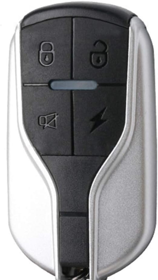
Image 5.1: Close-up view of the remote control, highlighting the function buttons.
- Lock Button (🔒): Press once to arm the alarm system. The vehicle may flash its lights once and emit a short beep. The alarm will activate if vibration is detected.
- Unlock Button (🔓): Press once to disarm the alarm system. The vehicle may flash its lights twice and emit two short beeps.
- Lightning Bolt Button (⚡): Press and hold to activate the alarm for vehicle locating or emergency. Press again to stop. This button may also function as a remote engine start if wired accordingly.
- Bell/Mute Button (🔖): Press once to mute the alarm temporarily or to locate your vehicle by flashing lights without sound.
5.1 Remote Engine Start/Stop (If Applicable)
If your system is wired for remote engine start, press the Lightning Bolt button twice quickly to start the engine. Press the Unlock button to stop the engine.
5.2 Vibration Sensitivity
The alarm system typically has a pre-set vibration sensitivity. Some models may allow adjustment by pressing specific button combinations (refer to specific product documentation if available). Excessive sensitivity can lead to false alarms.
6. Maintenance
Regular maintenance ensures the longevity and reliability of your alarm system.
- Cleaning: Keep the main unit and remote controls clean and free from dust and debris. Use a soft, dry cloth. Avoid harsh chemicals.
- Battery Replacement (Remote): If the remote control range decreases or it stops responding, the internal battery may need replacement. Typically, these remotes use small button-cell batteries (e.g., CR2032). Refer to the remote's casing for instructions on opening and battery type.
- Wiring Inspection: Periodically check all wiring connections for corrosion, looseness, or damage. Ensure insulation is intact.
- Function Test: Regularly test the alarm system by arming it and gently shaking the vehicle to ensure the alarm activates correctly.
7. Troubleshooting
If you encounter issues with your alarm system, refer to the following common problems and solutions:
| Problem | Possible Cause | Solution |
|---|---|---|
| Alarm does not arm/disarm | Remote battery low/dead Remote out of range Main unit power issue | Replace remote battery Move closer to the vehicle Check main unit wiring and power supply |
| False alarms | High vibration sensitivity Loose mounting of main unit Environmental factors (wind, heavy vehicles passing) | Adjust sensitivity (if possible) Securely mount the main unit Consider mounting location |
| Alarm does not sound | Speaker wire disconnected Main unit malfunction | Check speaker wiring Contact customer support if wiring is correct |
| Remote engine start not working | Incorrect wiring for remote start Vehicle not compatible | Verify wiring connections for remote start function Confirm vehicle compatibility with remote start feature |
8. Safety Information
- Always disconnect the vehicle's battery before performing any electrical installation or maintenance.
- Ensure all wiring is correctly insulated and secured to prevent short circuits, electrical fires, or damage to components.
- Do not attempt to modify the alarm system. Unauthorized modifications can lead to malfunction, damage, or void the warranty.
- Keep remote controls away from children.
- Do not immerse the main unit or remote controls in water. While the main unit is water-resistant, it is not waterproof.
9. Warranty and Support
For warranty information, please refer to the terms and conditions provided by your retailer at the time of purchase. If you require technical support or have questions not covered in this manual, please contact the WINOMO customer service department or your authorized dealer.
Please have your product model number (Z24C0214U7DTQ0CQIPNAK) and purchase details ready when contacting support.