1. Introduction
This manual provides essential information for the installation, operation, and maintenance of the FERMAX 4825 DUOX Plus DIN10 24VDC 2.5A Power Supply with Filter. This unit is designed to provide stable and reliable power to various FERMAX DUOX Plus intercom system components.
The FERMAX 4825 is a DIN rail mountable power supply, featuring a 24V DC output at 2.5A, and an integrated filter for optimal performance within DUOX Plus systems. It is protected by an electronic fuse to ensure safety and longevity.
2. Product Overview
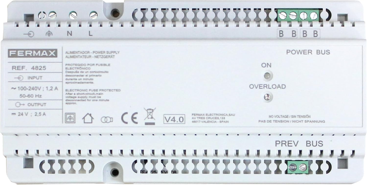
Figure 1: Front view of the FERMAX 4825 DUOX Plus DIN10 Power Supply. The image displays the input terminals (N, L), output terminals (24V, 2.5A), Power Bus and Prev Bus terminals, and LED indicators for ON and OVERLOAD status. Key specifications like input voltage (100-240V; 1.2A, 50-60Hz) and output voltage (24V; 2.5A) are visible, along with the FERMAX brand logo and model number REF. 4825.
The FERMAX 4825 power supply is equipped with the following key features:
- Input Voltage: Operates with an input voltage range of 100-240V AC, 50-60 Hz, ensuring compatibility with standard electrical grids.
- Output Voltage: Provides a stable 24V DC output at 2.5A, suitable for various DUOX Plus components.
- Electronic Fuse Protection: Features an electronic fuse that protects the unit from short circuits. In case of a short circuit, the primary voltage supply must be disconnected for approximately one minute to reset the protection.
- Integrated Filter: Includes an integrated filter to enhance signal quality and system stability within DUOX Plus installations.
- DIN10 Mounting: Designed for easy installation on a DIN rail, making it suitable for electrical cabinets and distribution boards.
- LED Indicators: Equipped with "ON" and "OVERLOAD" LED indicators for quick status monitoring.
3. Safety Instructions
- Installation must be performed by qualified personnel in accordance with local electrical codes and regulations.
- Ensure the main power supply is disconnected before performing any installation, wiring, or maintenance.
- Do not expose the unit to moisture, water, or extreme temperatures.
- Do not open the casing of the power supply. There are no user-serviceable parts inside.
- Verify input voltage and frequency match the specifications of the power supply before connection.
4. Setup and Installation
4.1 Mounting
- Select a suitable location within an electrical cabinet or distribution board that allows for proper ventilation.
- Mount the FERMAX 4825 power supply onto a standard DIN rail. Ensure it is securely fastened.
4.2 Wiring Connections
Refer to Figure 1 for terminal locations.
- Input Power (AC): Connect the main AC power supply to the terminals labeled N (Neutral) and L (Line). Ensure proper polarity. The input range is 100-240V AC, 50-60 Hz.
- Ground Connection: Connect the protective earth ground to the terminal marked with the ground symbol.
- Output Power (DC): Connect the DUOX Plus equipment requiring 24V DC power to the terminals labeled + and - under "OUTPUT". The output is 24V DC, 2.5A.
- Power Bus / Prev Bus: Connect the DUOX Plus system bus lines to the "POWER BUS" and "PREV BUS" terminals as per your specific DUOX Plus system diagram. These terminals are typically used for data and power distribution within the intercom system.
Important: Double-check all wiring connections before applying power to prevent damage to the unit or connected equipment.
5. Operating Instructions
5.1 Powering On
- After ensuring all connections are secure and correct, switch on the main AC power supply to the unit.
- The "ON" LED indicator on the front panel should illuminate, indicating that the power supply is active and providing output voltage.
5.2 Status Indicators
- ON LED: Illuminates when the power supply is receiving input power and operating normally.
- OVERLOAD LED: Illuminates if the output current exceeds the rated 2.5A, or if a short circuit is detected on the output.
6. Maintenance
The FERMAX 4825 power supply is designed for reliable, long-term operation with minimal maintenance. Follow these guidelines:
- Cleaning: Periodically clean the exterior of the unit with a soft, dry cloth. Do not use liquid cleaners or solvents. Ensure the unit is powered off before cleaning.
- Ventilation: Ensure that the ventilation openings are not obstructed to allow for proper air circulation and cooling.
- Connection Checks: Occasionally check all wiring connections to ensure they remain tight and secure.
7. Troubleshooting
- No "ON" LED illumination:
- Check if the main AC power supply is connected and active.
- Verify the input wiring (N, L) is correct and secure.
- "OVERLOAD" LED illuminates:
- This indicates an overcurrent condition or a short circuit on the 24V DC output or connected DUOX Plus bus lines.
- Immediately disconnect the main AC power supply to the unit.
- Inspect all connected DUOX Plus equipment and wiring for short circuits or excessive load.
- After resolving the issue, wait approximately one minute before reconnecting the main AC power supply to allow the electronic fuse to reset.
- If the problem persists, the connected equipment may be drawing too much current, or the power supply itself may be faulty.
- No Voltage / Sin Tensión / Nicht Spannung:
- This label on the unit indicates the absence of voltage. If the "ON" LED is off and there is no output, refer to the "No 'ON' LED illumination" troubleshooting steps.
8. Specifications
| Feature | Specification |
|---|---|
| Brand | FERMAX |
| Model | 4825 (F04825) |
| Input Voltage | 100-240V AC |
| Input Frequency | 50-60 Hz |
| Input Current | 1.2 A |
| Output Voltage | 24V DC |
| Output Current | 2.5 A |
| Power Output | 60 Watts |
| Cooling Method | Air Cooling / Ventilator |
| Mounting | DIN Rail (DIN10) |
| Protection | Electronic Fuse Protected |
| Weight | 96 Grams |
Note: Specifications are subject to change without notice.
9. Warranty and Support
FERMAX products are manufactured to high-quality standards. This product includes a satisfaction guarantee and quality customer service.
For technical support, warranty claims, or further assistance, please contact your local FERMAX distributor or visit the official FERMAX website. Please have your product model (4825) and serial number (if applicable) ready when contacting support.
For more information, you can visit the FERMAX official website.


