1. Introduction
Thank you for choosing the EASE2U E 4-in-1 LED 32W Emergency Strobe Light Bar. This product is designed to provide high-visibility warning and hazard lighting for various vehicles, including off-road vehicles, ATVs, and trucks. This manual provides essential information for the safe installation, operation, and maintenance of your new strobe light system. Please read these instructions thoroughly before installation and use.
2. Safety Information
Always observe the following safety precautions to prevent injury and damage to the product or vehicle:
- Ensure the vehicle's power is disconnected before beginning any installation or wiring work.
- Verify that the power source voltage matches the product's specifications (12V/24V).
- Do not look directly into the LED lights when they are active, as this may cause temporary vision impairment.
- Mount the lights securely to prevent detachment during vehicle operation.
- Ensure all wiring connections are properly insulated and protected from environmental elements.
- Consult local regulations regarding the use of emergency warning lights on public roads.
3. Package Contents
Please check the package to ensure all items are present:
- 4 x COB-LED 8W Mini Light Bars
- 1 x On/Off Switch and Mode Switch Controller
- 8 x Mounting Screws

Image: The complete package includes four blue LED strobe light units.
4. Product Features
- High Visibility: 32 watts of powerful COB LED illumination for superior warning.
- Durable Construction: Die-casting aluminum-alloy housing ensures longevity.
- Weather Resistant: IP65 waterproof rating allows for safe exterior mounting in challenging conditions.
- Versatile Mounting: Supports both roof and side installation with removable and adjustable brackets.
- Multiple Flash Patterns: Features 7 selectable flash patterns, including a steady-on mode.
- Easy Control: Patterns are easily changed via a dedicated button on the included controller.
- Flexible Power: Can be powered by a cigarette lighter or other 12V/24V power sources.
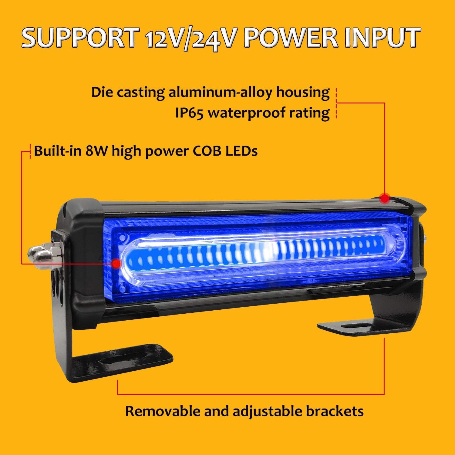
Image: A single strobe light unit highlighting its COB LED design, IP65 waterproof rating, and durable housing.
5. Technical Specifications
| Feature | Specification |
|---|---|
| Brand | EASE2U E |
| Model Number | EUCOBAW4 |
| Color | Blue |
| Light Source Type | COB LED |
| Wattage | 32 watts (8W per light bar) |
| Voltage | 12V / 24V |
| Waterproof Rating | IP65 |
| Lens Material | Polycarbonate |
| Mounting Type | Surface Mount (with/without brackets) |
| Item Weight | 2.92 pounds |
| Package Dimensions | 12.6 x 7.2 x 3.31 inches |

Image: Detailed dimensions of a single strobe light unit.
6. Installation Instructions
6.1. Mounting the Light Bars
The light bars offer two primary mounting methods:
- Surface Mounting with Built-in Screws: Directly attach the light bar to the desired surface using the built-in screws. The location of these screws can be adjusted.
- Bracket Mounting: Remove the brackets from the light bars. Mount the brackets to the vehicle surface first, then install the light bars onto the brackets. This method provides additional flexibility for positioning.
Ensure the mounting location is flat, stable, and allows for proper light projection. The lights can be installed on the roof or around the sides of the vehicle.

Image: Illustration of the two-way mounting solutions for the strobe lights.
6.2. Wiring Connections
The light system is designed for simple plug-and-play installation. The wires between the individual light bars are pre-connected.
- Identify the main wiring harness connected to the controller.
- Connect the main power input of the harness to your vehicle's 12V or 24V power source. This can be done via the included cigarette lighter plug for temporary use or by hardwiring to a suitable power supply for permanent installation.
- Ensure all connections are secure and properly insulated to prevent short circuits and water ingress.

Image: Wiring diagram showing the connections and cable lengths for the light system.
7. Operation
The EASE2U E strobe light system is controlled by a single switch unit.
7.1. Powering On/Off
Locate the controller unit. The red rocker switch on the controller is the main power On/Off switch. Flip the switch to the 'I' position to turn the lights on, and to the 'O' position to turn them off.
7.2. Changing Flash Patterns
The round red button on the controller is the pattern switch. Press this button repeatedly to cycle through the 7 available flash patterns. The system will remember the last selected pattern when powered off and on again.
The 7 flash patterns include various strobe sequences and a steady-on mode.

Image: The controller unit with clearly marked power and pattern switches.
8. Maintenance
To ensure optimal performance and longevity of your strobe lights, follow these maintenance guidelines:
- Cleaning: Regularly clean the lens and housing with a soft, damp cloth. Avoid abrasive cleaners or solvents that could damage the polycarbonate lens or housing finish.
- Inspection: Periodically check all mounting hardware for tightness and ensure the lights are securely attached. Inspect wiring for any signs of wear, fraying, or damage.
- Waterproofing: While the lights are IP65 rated, ensure that all cable entries and connections remain sealed to maintain water resistance.
9. Troubleshooting
If you encounter issues with your strobe light system, refer to the following table for common problems and solutions:
| Problem | Possible Cause | Solution |
|---|---|---|
| Lights do not turn on | No power supply Loose wiring connection Blown fuse | Check power source and ensure it's active. Verify all wiring connections are secure. Check vehicle's fuse box and replace any blown fuses. |
| Lights flicker or dim | Insufficient power Poor connection Voltage drop | Ensure adequate power supply. Check for corrosion on terminals. Tighten all connections. Verify wiring gauge is sufficient for the length and current. |
| Cannot change flash patterns | Faulty pattern switch Controller malfunction | Ensure the pattern switch is being pressed firmly. If the issue persists, contact customer support. |
| Water inside the lens | Compromised seal Improper installation | Inspect seals around the lens and housing for damage. Re-seal if necessary. Ensure mounting screws are not overtightened, which can warp the housing. |
10. Warranty and Support
For warranty information or technical support, please refer to the product packaging or contact EASE2U E customer service directly. Keep your purchase receipt as proof of purchase for any warranty claims.