1. Introduction
The Klein Tools Scout Pro 3 Cable Tester with Test + Map Remote Kit is a versatile instrument designed for locating and testing various types of cables. This device is engineered to provide accurate identification and verification of voice (RJ11/12), data (RJ45), and video (F-connector) coaxial cables. It also features Power over Ethernet (PoE) detection and comprehensive wiremap testing capabilities, ensuring reliable cable installations.
The backlit display enhances readability in various lighting conditions, making it suitable for professional use in diverse environments. This manual provides detailed instructions for the proper setup, operation, and maintenance of your Scout Pro 3 Cable Tester.
2. Safety Information
WARNING: Read, understand, and follow all instructions, warnings, and cautions before using this product. Failure to do so may result in electric shock, fire, or serious injury.
- Always inspect the tester and cables for damage before use. Do not use if damaged.
- Do not use the tester on live circuits or energized cables unless specifically designed for such use (e.g., PoE detection).
- Ensure proper battery installation and replacement. Use only specified battery types.
- Keep the device dry. Do not expose to rain or moisture.
- Do not attempt to modify or repair the tester. Refer all servicing to qualified personnel.
- Wear appropriate personal protective equipment (PPE) when working with electrical systems.
3. Package Contents
The Klein Tools Scout Pro 3 Cable Tester with Test + Map Remote Kit includes the following components:
- 1 x Scout Pro 3 Tester
- 1 x Self-storing Test+Map remote (#1)
- 5 x Test+Map remotes (#2-6)
- 7 x Female-to-female coax barrel adapters
- 7 x Male-to-female coax barrel adapters
- 7 x RJ45 jumper cables (6-Inch)
- 2 x RJ11 jumper cables (6-Inch)
- 2 x RJ12 jumper cables (6-Inch)
- 1 x 9V battery
- 1 x Convenient carrying case

Figure 3.1: Complete contents of the Scout Pro 3 Cable Tester kit.
4. Setup
4.1 Battery Installation
The Scout Pro 3 Tester requires 4 AA batteries for operation. To install or replace batteries:
- Locate the battery compartment cover on the back of the tester.
- Use a screwdriver to loosen the screw securing the cover.
- Remove the cover and insert the 4 AA batteries, ensuring correct polarity (+/-) as indicated inside the compartment.
- Replace the cover and tighten the screw.

Figure 4.1: Battery compartment for 4 AA batteries.
4.2 Connecting Remotes
The kit includes a self-storing Test+Map remote (#1) and five additional Test+Map remotes (#2-6). These remotes are used for identifying cable runs and verifying wiremaps.
- For basic testing, the self-storing remote can be detached from the main unit and connected to the far end of the cable.
- For identifying multiple cable runs, connect the numbered Test+Map remotes (#2-6) to the far ends of the cables you wish to test. The tester will display the ID number of the connected remote.
5. Operating Instructions
5.1 General Operation and Display
The Scout Pro 3 features a large, backlit LCD for clear display of test results. Press the power button to turn the unit on. The display will show various indicators including voltage warning, shield detection, and low battery status.

Figure 5.1: Scout Pro 3 Tester with its backlit LCD display.
5.2 Versatile Connection Testing
The Scout Pro 3 tests voice (RJ11/12), data (RJ45), and video (F-connector) coax connections. Connect the cable to the appropriate port on the tester and the remote unit.

Figure 5.2: Input ports for various cable types.
5.3 Comprehensive Wire Testing (Wiremap)
The tester performs wiremap testing to check for common cable faults such as Miswires, Split Pairs, Short Faults, Open Faults, and Shield issues. The results are displayed clearly on the LCD.

Figure 5.3: Display showing a 'Fail Short' condition.

Figure 5.4: Display showing a 'Pass X-over' condition with remote ID.
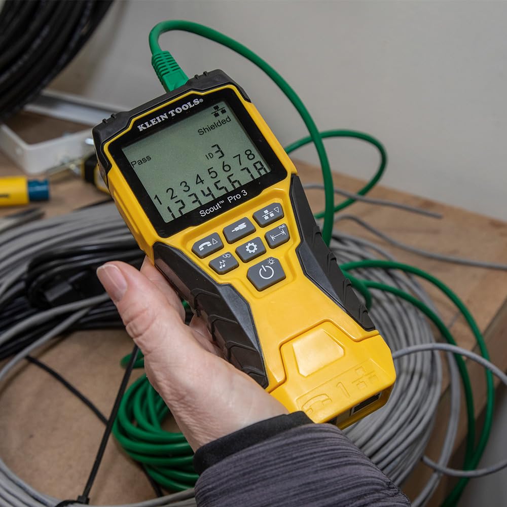
Figure 5.5: Display showing a 'Pass Shielded' condition.
5.4 Power over Ethernet (PoE) Detection
The Scout Pro 3 can detect, identify, and test Power over Ethernet (PoE) presence, including PoE+ and various wiring types (A wiring, B wiring), and voltage levels. This feature is crucial for verifying power delivery in network installations.

Figure 5.6: Display showing PoE voltage detection.

Figure 5.7: Display showing a 'Fail PoE' condition.
5.5 Cable Length Measurement
The tester measures cable length up to 2000 feet (610 meters), providing accurate distance information for cable runs.

Figure 5.8: Cable length measurement display.
5.6 Cable Tracing (Toning)
The multi-style tone generator allows for tracing cables, wire pairs, and individual conductor wires. This feature requires an analog probe (Klein Tools Cat. No. VDV500-123, sold separately).
The tester can tone wires from 800 Hz to 1500 Hz and can tone individual wires, pairs, or all 8 wires. It also supports toning RJ11/RJ12 terminated cables.
5.7 Hub Blink Mode
The Hub Blink mode identifies the port location on a hub or a switch by causing the corresponding port LED to blink, simplifying cable identification in crowded network environments.

Figure 5.9: Tester in Hub Blink mode.
6. Maintenance
6.1 Cleaning
Ensure the tester is turned off and disconnected from all cables before cleaning. Use a clean, dry, lint-free cloth to wipe the unit. Do not use abrasive cleaners or solvents.
6.2 Battery Replacement
Replace batteries when the low battery indicator appears on the display. Refer to Section 4.1 for battery installation instructions. Always dispose of old batteries responsibly according to local regulations.
6.3 Storage
When not in use, store the tester and its accessories in the provided carrying case in a cool, dry place, away from direct sunlight and extreme temperatures. If storing for extended periods, remove the batteries to prevent leakage.
7. Troubleshooting
This section addresses common issues you might encounter with your Scout Pro 3 Cable Tester.
| Problem | Possible Cause | Solution |
|---|---|---|
| Tester does not power on. | Dead or incorrectly installed batteries. | Check battery polarity or replace batteries (refer to Section 4.1). |
| Inaccurate cable test results (e.g., "Fail Short", "Open"). | Damaged cable, incorrect termination, or faulty remote. | Inspect the cable for visible damage. Re-terminate the cable ends. Try a different remote if available. |
| PoE detection fails or shows incorrect voltage. | No PoE power on the line, incorrect PoE standard, or tester not fully connected. | Verify the PoE source is active. Ensure the cable is fully seated in the tester's RJ45 port. |
| Cable length measurement is inconsistent. | Cable impedance variations, external interference, or damaged cable. | Ensure the cable is not coiled tightly. Test a known good cable for comparison. Minimize external electrical interference. |
| Toning function not working. | Analog probe not connected or faulty, or cable not properly connected. | Ensure the analog probe (VDV500-123) is correctly connected and functioning. Verify cable connection to the tester. |
8. Specifications
| Feature | Detail |
|---|---|
| Model Number | VDV501-853 |
| Product Dimensions | 6.9 x 3.2 x 1.5 inches |
| Item Weight | 1.2 Pounds |
| Power Source | Battery Powered |
| Batteries Required | 4 AA batteries |
| Cable Types Tested | Voice (RJ11/12), Data (RJ45), Video (F-connector) Coax |
| Cable Length Measurement | Up to 2000 feet (610 meters) |
| PoE Detection | Yes (Detects, identifies, and tests PoE, PoE+, A wiring, B wiring, and voltage) |
| Wiremap Testing | Miswires, Split Pairs, Short Faults, Open Faults, Shield issues |
| Tone Generator | Multi-style (requires analog probe VDV500-123, sold separately) |
9. Warranty and Support
Klein Tools stands behind the quality of its products. For detailed warranty information, product registration, and customer support, please visit the official Klein Tools website or contact their customer service department.
You can also refer to the official Instructions for Use (IFU) document for more comprehensive details:


