1. Introduction
The WinAPEX ET8104 is a portable, auto-ranging digital multimeter designed for accurate measurement of various electrical parameters. It features a clear LCD color screen, True RMS measurement, and a built-in flashlight, making it suitable for both professional and DIY electrical tasks. This manual provides essential information for safe and effective use of your multimeter.
2. Safety Information
Always read and understand all safety warnings and operating instructions before using this instrument.
- Do not exceed the maximum input values for any function.
- Do not use the meter if it is damaged or if the test leads are damaged.
- Exercise extreme caution when working with voltages above 30V AC RMS, 42V peak, or 60V DC. These voltages pose a shock hazard.
- Always disconnect power to the circuit and discharge all high-voltage capacitors before measuring resistance, continuity, diodes, or capacitance.
- Ensure the correct function and range are selected before making measurements.
- Keep fingers behind the probe barriers during measurement.
- Replace the battery as soon as the low battery indicator appears to ensure accurate readings.
3. Package Contents
Verify that all items listed below are included in your package:
- 1 x WinAPEX ET8104 Digital Multimeter
- 1 x K-type Thermocouple (TP01)
- 1 x Pair of Test Leads
- 1 x User Manual
4. Product Overview
The WinAPEX ET8104 features a compact design with a clear LCD display and intuitive controls. The protective casing enhances durability and provides dust resistance.
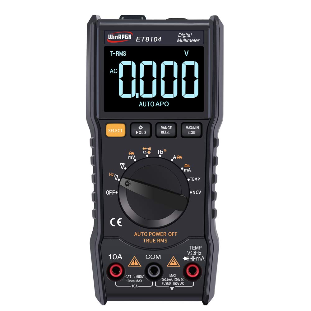
Figure 4.1: Front view of the WinAPEX ET8104 Digital Multimeter, showing the display, rotary dial, and function buttons.

Figure 4.2: Front and rear view of the WinAPEX ET8104 Digital Multimeter, highlighting its robust protective casing.

Figure 4.3: The WinAPEX ET8104 Multimeter displaying a summary of its measurement capabilities.
4.1 Display and Controls
- LCD Display: Shows measurement readings, unit symbols, and function indicators. Features a backlight for low-light conditions.
- Rotary Dial: Used to select the desired measurement function (e.g., V~, V-, Ω, A~, A-, Hz, Temp, NCV, OFF).
- SELECT Button: Toggles between AC/DC modes or different sub-functions within a rotary dial setting (e.g., AC Voltage / DC Voltage).
- HOLD Button: Freezes the current reading on the display. Press again to release.
- RANGE/RELA Button: Manually selects measurement range or activates relative measurement mode.
- MAX/MIN Button: Displays the maximum or minimum measured value.
- Input Jacks: Terminals for connecting test leads (COM, VΩHz, 10A, mA).
- Flashlight: Integrated flashlight for illuminating work areas.
- NCV Sensor: Non-Contact Voltage detection area.
5. Setup
5.1 Battery Installation
- Ensure the multimeter is turned OFF.
- Locate the battery compartment on the back of the device.
- Use a screwdriver to open the battery cover.
- Insert the required batteries (typically AAA or 9V, refer to the battery compartment label) observing correct polarity.
- Replace the battery cover and secure it with the screw.
5.2 Connecting Test Leads
Always connect the black test lead to the COM (Common) jack. Connect the red test lead to the appropriate input jack based on the measurement function:
- For Voltage, Resistance, Capacitance, Frequency, Diode, Continuity, and Temperature measurements: Connect the red lead to the VΩHz jack.
- For Current measurements up to 10A: Connect the red lead to the 10A jack.
- For Current measurements in milliampere range: Connect the red lead to the mA jack.
6. Operating Instructions
The ET8104 features auto-ranging, simplifying operation by automatically selecting the correct measurement range. For specific functions, use the rotary dial and the SELECT button.
6.1 Measuring AC/DC Voltage (V~ / V-)
- Turn the rotary dial to V~ or V-. The meter will automatically detect AC or DC voltage.
- Connect the black test lead to the COM jack and the red test lead to the VΩHz jack.
- Connect the test probes in parallel to the circuit or component under test.
- Read the voltage value on the display.
6.2 Measuring Resistance (Ω)
- Turn the rotary dial to Ω.
- Connect the black test lead to COM and the red test lead to VΩHz.
- Ensure the circuit is de-energized before connecting the probes across the component.
- Read the resistance value on the display.
6.3 Measuring Capacitance
- Turn the rotary dial to the capacitance symbol (typically || or F).
- Connect the black test lead to COM and the red test lead to VΩHz.
- Ensure the capacitor is fully discharged before connecting the probes.
- Connect the probes across the capacitor terminals.
- Read the capacitance value on the display.
6.4 Non-Contact Voltage (NCV) Detection
The NCV function allows for detection of AC voltage without direct contact with wires.
- Turn the rotary dial to NCV.
- Place the NCV sensor (located at the top of the meter) near the wire or outlet.
- The meter will emit an audible beep and the LED indicator will flash if AC voltage is detected. The frequency of beeps and flashes increases with stronger voltage.

Figure 6.1: Demonstrating the NCV function and integrated flashlight.
6.5 Temperature Measurement
- Turn the rotary dial to TEMP.
- Connect the K-type thermocouple to the VΩHz and COM jacks, observing polarity.
- Place the thermocouple probe on or near the object whose temperature is to be measured.
- Read the temperature value on the display. Use the SELECT button to switch between Celsius (°C) and Fahrenheit (°F).
6.6 Other Functions
- Flashlight: Press the flashlight button (if available, or a dedicated button) to turn on/off the integrated flashlight.
- Data Hold: Press the HOLD button to freeze the current reading on the display.
- MAX/MIN: Press the MAX/MIN button to cycle through maximum, minimum, and current readings.
- Auto Power Off: The meter will automatically power off after a period of inactivity to conserve battery life.
7. Maintenance
7.1 Cleaning
Wipe the case with a damp cloth and mild detergent. Do not use abrasives or solvents. Keep the input terminals free of dirt and moisture.
7.2 Battery Replacement
When the low battery indicator appears on the display, replace the batteries immediately to ensure accurate measurements. Follow the battery installation steps in Section 5.1.
7.3 Fuse Replacement
If the current measurement function stops working, the fuse may need replacement. Refer to the specifications for the correct fuse type and rating. Fuse replacement should only be performed by qualified personnel.
8. Troubleshooting
| Problem | Possible Cause | Solution |
|---|---|---|
| Meter does not power on | Dead batteries or incorrect battery installation | Check battery polarity or replace batteries. |
| No reading or 'OL' displayed | Incorrect function/range selected, open circuit, or over-range input | Verify function selection, check circuit connections, or ensure input is within range. |
| Inaccurate readings | Low battery, damaged test leads, or external interference | Replace batteries, check/replace test leads, move away from strong electromagnetic fields. |
| Current measurement not working | Blown fuse | Replace the fuse (refer to Section 7.3). |
9. Specifications
| Parameter | Value |
|---|---|
| Brand | WinAPEX |
| Model | ET8104 |
| Display Count | 9999 |
| Power Source | Battery operated |
| Color | Black |
| Measurement Method | Double integral A/D conversion |
| Sampling Rate | Approx. 3 times/second |
| Over-range Display | "0L" |
| Working Environment | 0~40°C, Relative humidity <80% |
| LCD Size | 49 x 32 mm (1.9 x 1.3 inches) |
| Product Size | 142 x 70 mm (5.6 x 2.8 inches) |
| Package Weight | 305g (10.8 ounces) |
| DC Voltage Accuracy | ±(1.2%+10) |
| AC Voltage Accuracy | ±(1.2%+10) |
| DC Current Range | 60mA/600mA/10A |
| DC Current Accuracy | ±(2.0%+30) for 10A, Resolution: 0.01A |
| AC Current Range | 60mA/600mA/10A |
| AC Current Accuracy | ±(2.0%+30) for 10A, Resolution: 0.01A |
| Resistance Range | 1000Ω / 10kΩ / 100kΩ / 1MΩ / 10MΩ / 100MΩ |
| Resistance Accuracy | 1000Ω: ±(0.8%+5); 10kΩ-10MΩ: ±(0.8%+3); 100MΩ: ±(2.5%+3) |
| Capacitance Range | 100nF/1000nF/10µF/100µF/1000µF/100mF |
| Capacitance Accuracy | 100nF-1000µF: ±(3.5%+20); 100mF: ±(5%+3) |
| Frequency Range | 10Hz/100Hz/1KHz/10KHz/100KHz/1MHz/10MHz |
| Frequency Accuracy | ±(0.1%+3) |
| Temperature Range | (-20-1000)°C / (0-1832)°F |
| Temperature Accuracy | °C: ±(1.0%+5) <400°C, ±(1.5%+15) ≥400°C; °F: ±(0.75%+5) <750°F, ±(1.5%+15) ≥750°F |
| NCV | Yes |
| True RMS | Yes |
| Auto Power Off | Yes |
| Data Hold | Yes |
| Backlight | Yes |
| Flashlight | Yes |
10. Warranty and Support
WinAPEX products are designed for reliability and performance. For warranty information or technical support, please refer to the warranty card included with your product or contact your local distributor. Keep your purchase receipt as proof of purchase.