Introduction
This manual provides detailed instructions for the safe and effective use of your JIFETOR 3-Way AC Manifold Gauge Set. This HVAC diagnostic and freon charging tool is designed for automotive and household air conditioning systems using R12, R22, R404A, and R134A refrigerants. Please read this manual thoroughly before operation to ensure proper usage and to prevent damage to the equipment or injury.
Packing List
Upon opening your JIFETOR 3-Way AC Manifold Gauge Set, please verify that all components listed below are present and in good condition:
- 1 x 3-Way Double Movement Brass Manifold AC Gauge (with blue low pressure gauge -30inHg~250PSI and red high pressure gauge 0~500PSI, Celsius unit, sight window, and hang hook)
- 3 x 5FT Color-Coded Hoses (Red, Blue, Yellow) with 1/4" female brass fittings
- 2 x AC R134A Quick Couplers (Red for high pressure, Blue for low pressure)
- 1 x Valve Core Accessories Kit
- 1 x Detailed Instruction Manual

Image: Contents of the JIFETOR 3-Way AC Manifold Gauge Set packaging.
Product Features
- AC Manifold Gauge: Features a 3-way double movement brass manifold, durable and anti-corrosion. The blue low-pressure gauge ranges from -30inHg to 250PSI, and the red high-pressure gauge ranges from 0 to 500PSI, both with Celsius units. The 2-3/4" large dials are easy to read with color-coded scales. A sight window on the manifold allows for better and easier monitoring of refrigerant charging and recovery. A built-in calibration screw and no-flutter pointer ensure measurement accuracy. Compatible with R12, R22, R404A, and R134A refrigerants.
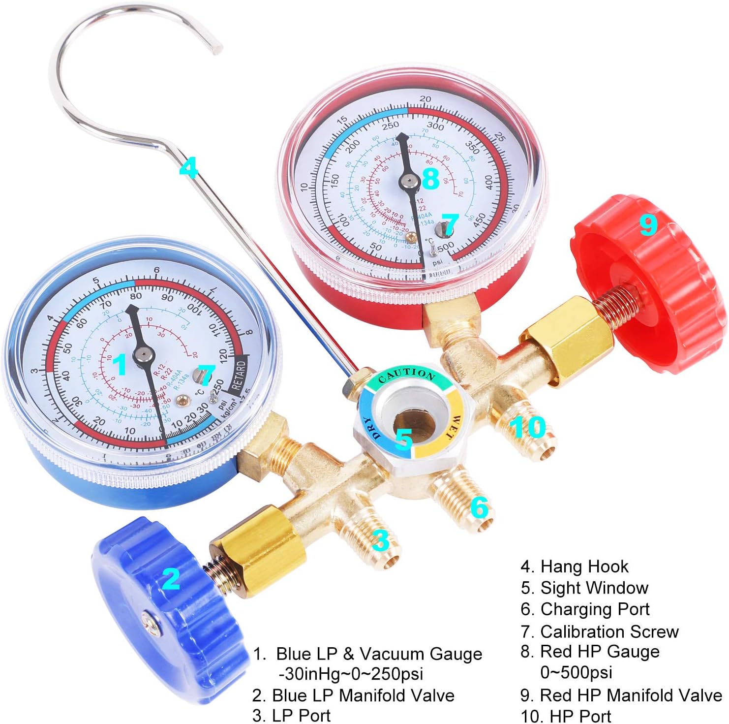
Image: Close-up of the AC Manifold Gauge with labeled components.
- 5FT Color-Coded Hoses: The freon charging kit includes three 5-foot hoses made from rubber nylon resin material, offering anti-corrosion properties, low fluid resistance, and high bearing pressure for durability and good air sealing. Maximum working pressure is 600PSI, and burst pressure is 3000PSI. Each hose end is equipped with 1/4" female brass fittings for easy connection. The red hose connects to the red gauge side 1/4" male flare to the red quick coupler, the blue to the blue, and the yellow hose connects the AC gauge middle charging port to a can tap or vacuum pump.
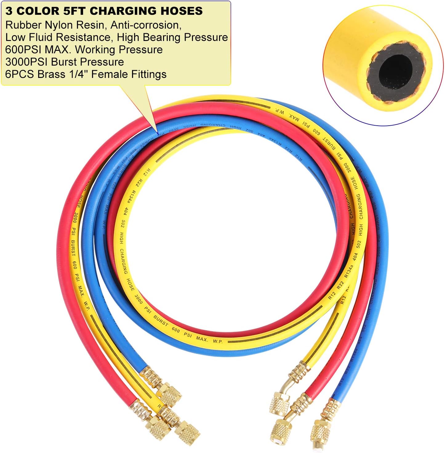
Image: The three color-coded 5-foot charging hoses.
- AC R134A Quick Couplers: Constructed from premium brass and aluminum, these quick couplers feature an accurate snap lock and anti-slip knurled grip ring for easy connection and disconnection. They are compatible with all models equipped with an R134A service port. The blue coupler connects to the AC suction service port, and the red one connects to the AC discharge service port. To connect, aim at the service port, push to connect, and lock. To disconnect, pull up the knurled grip ring and lift.

Image: R134A quick couplers connected to an automotive AC system.
- Valve Core Accessories Kit: A bag containing various valve core accessories is included with the AC refrigerant manifold charging kit. Please note: This kit is sold without a can tap, valve core remover, and ACME adapter, but some packages may include these as a bonus. Refer to your actual package contents.

Image: Various accessories included with the manifold gauge set.
Setup
Proper setup is crucial for accurate readings and safe operation. Follow these steps to prepare your manifold gauge set:
- Connect Hoses to Manifold: Attach the red hose to the high-pressure port (red knob) on the manifold, the blue hose to the low-pressure port (blue knob), and the yellow hose to the central service/charging port. Ensure all connections are finger-tight, then use a wrench to tighten them securely.
- Connect Quick Couplers: Attach the red R134A quick coupler to the free end of the red hose and the blue R134A quick coupler to the free end of the blue hose.
- Prepare Can Tap (if applicable): If using a refrigerant can, attach the can tap to the yellow hose. Ensure the piercing pin is retracted before attaching to the can.
- Hang the Manifold: Use the integrated hook to hang the manifold gauge set in a secure and visible location, such as under the vehicle's hood, away from moving parts and heat sources.

Image: Manifold gauge set properly hung in an engine bay.
For a visual guide on connecting the components, please refer to the following video:
Video: An overview of the JIFETOR 3-Way AC Manifold Gauge Set, demonstrating its components and basic setup.
Operating Instructions
This section outlines general operating procedures for common AC system tasks. Always consult a professional service manual for your specific vehicle or appliance for detailed, model-specific instructions.
General Connection Diagram

Image: Schematic diagram for connecting the manifold gauge set for AC service.
1. Pressure Reading / Diagnostic Check
- Ensure both high (red) and low (blue) side valves on the manifold are closed.
- Connect the blue quick coupler to the low-pressure service port (usually marked 'L' or smaller diameter) and the red quick coupler to the high-pressure service port (usually marked 'H' or larger diameter) of the AC system.
- Start the vehicle engine and turn on the AC to maximum cooling. Allow the system to stabilize for a few minutes.
- Read the pressures on both the blue (low side) and red (high side) gauges. Compare these readings to the manufacturer's specifications for your system and refrigerant type.
2. Evacuation (Vacuum)
- Connect the blue and red quick couplers to the AC system service ports.
- Connect the yellow hose to a vacuum pump.
- Open both the high (red) and low (blue) side valves on the manifold.
- Start the vacuum pump. Monitor the low-pressure gauge; it should drop into a vacuum (below 0 PSI, into the negative pressure range).
- Allow the pump to run for the recommended time (refer to your system's service manual) to ensure complete evacuation of air and moisture.
- Once evacuation is complete, close both manifold valves, then turn off the vacuum pump. Observe the low-pressure gauge for any rise in pressure, which would indicate a leak.
3. Refrigerant Charging
- After successful evacuation and leak check, ensure both manifold valves are closed.
- Connect the yellow hose to the refrigerant source (can or tank) via a can tap or appropriate adapter.
- Purge the yellow hose: Slightly open the refrigerant source valve, then briefly loosen the yellow hose connection at the manifold to release a small amount of refrigerant, purging air from the hose. Retighten immediately.
- Start the vehicle engine and turn on the AC to maximum cooling.
- Slowly open the low-side (blue) manifold valve to allow refrigerant to enter the system. Monitor the low-side pressure gauge.
- Add refrigerant in small increments, allowing the system to stabilize between additions. Do not overcharge the system. Refer to your system's specifications for the correct refrigerant amount.
- Once the desired pressure is reached, close the low-side manifold valve and the refrigerant source valve.
- Disconnect the quick couplers from the service ports.
Maintenance
Regular maintenance ensures the longevity and accuracy of your JIFETOR AC Manifold Gauge Set:
- Cleaning: After each use, wipe down the manifold, gauges, and hoses with a clean, dry cloth to remove any refrigerant residue or dirt.
- Hose Inspection: Periodically inspect hoses for cracks, cuts, or signs of wear. Replace damaged hoses immediately to prevent leaks.
- Gauge Calibration: The gauges feature a built-in calibration screw. If you suspect inaccuracy, consult a professional for calibration or follow specific calibration procedures if you have the necessary equipment.
- Storage: Store the manifold gauge set in its original case in a clean, dry environment, away from direct sunlight and extreme temperatures. Ensure all valves are closed and hoses are properly coiled to prevent kinking.
Troubleshooting
If you encounter issues with your JIFETOR AC Manifold Gauge Set, consider the following common problems and solutions:
| Problem | Possible Cause | Solution |
|---|---|---|
| Inaccurate Gauge Readings | Gauge out of calibration; internal damage; incorrect refrigerant type selected. | Check calibration screw; ensure correct refrigerant scale is used; contact support for repair or replacement. |
| Refrigerant Leaks | Loose connections; damaged hoses or O-rings; faulty quick couplers. | Tighten all connections; inspect hoses and O-rings for damage and replace if necessary; check quick couplers for proper sealing. |
| Difficulty Connecting Quick Couplers | Service port obstructed or damaged; quick coupler mechanism stuck. | Ensure service port is clean; lubricate quick coupler mechanism; replace quick coupler if damaged. |
If you cannot resolve the issue using the troubleshooting guide, please contact JIFETOR customer service for further assistance.
Specifications
- Manufacturer: JIFETOR
- Model: JT009S3-2
- Low Pressure Gauge Range: -30inHg to 250PSI
- High Pressure Gauge Range: 0 to 500PSI
- Refrigerant Compatibility: R12, R22, R404A, R134A
- Hose Length: 5 feet (1.5 meters)
- Hose Working Pressure: 600PSI
- Hose Burst Pressure: 3000PSI
- Hose Fittings: 1/4" Female Brass
- Quick Coupler Type: R134A (Red for High, Blue for Low)
- Item Weight: 1.25 kg
- Parcel Dimensions: 23.49 x 17.5 x 7.9 cm
Warranty and Support
JIFETOR offers a satisfactory customer service experience for your complete AC manifold gauge set. This product is perfect for automotive and household air conditioner evacuation/vacuum, diagnostic checks, coolant charging, and recovery.
- Refund Policy: 30 days full refund with returned undamaged JIFETOR product.
- Warranty: Any quality-related problem within 1 year, we will replace the fittings for free or provide a refund.
- Customer Service: For any questions or concerns, please feel free to contact us by email or through the Amazon message system. We aim to reply as soon as possible, typically within 24 hours.