1. Introduction
This manual provides comprehensive instructions for the setup, operation, and maintenance of the Matek Systems F411-WING STM32F411 Flight Controller. Designed for fixed-wing RC airplanes, this flight controller integrates essential components for stable and reliable flight control, including an IMU, barometer, and OSD.

Image 1.1: The Matek Systems F411-WING Flight Controller package, showing the main board, mounting hardware, and documentation.
2. Features
The F411-WING Flight Controller is equipped with a robust set of features to enhance your fixed-wing RC experience:
- High-Performance MCU: 100MHz STM32F411 for rapid processing.
- Integrated IMU: MPU6000 accelerometer/gyro (SPI) for precise attitude sensing.
- Barometric Sensor: BMP280 (I2C) for accurate altitude hold.
- On-Screen Display (OSD): INAV OSD with AT7456E chip for real-time flight data overlay.
- Connectivity: VCP & 2x UARTs for peripheral connections.
- Motor & Servo Outputs: Supports 2x Motors and 5x Servos.
- I2C Port: 1x I2C for external sensors like GPS or compass.
- Status LEDs: 3x LEDs for FC STATUS (Blue, Red) and 3.3V indicator (Red).
- SBUS Inverter: Built-in inverter for SBUS input (UART1-RX).
- Flexible Serial Ports: SoftSerial_Tx1 on ST1 pad by default, PPM on ST1 pad with softserial disabled.
- Battery Voltage Sensor: Integrated 1:10 (Scale 1100) sensor.
- Peripheral Support: WS2812 LED Strip and Beeper support.
- Firmware Compatibility: Pre-flashed with INAV Flight firmware, Target: MATEKF411.
- Power Distribution Board (PDB):
- Input voltage range: 6.5~30V (2~6S LiPo) with TVS protection.
- 2x ESC power pads.
- Current Sensor: 78A, 3.3V ADC, Scale 423.
- BEC Outputs:
- BEC 5V: 2 Amps continuous, for FC, Receiver, OSD, Camera, Buzzer, LED Strip, GPS.
- BEC Vx: 3 Amps continuous, voltage adjustable (5V Default, 6V via jumper), for Servos.
- BEC 3.3V: 200mA continuous, for Baro/Compass module, OLED, Spektrum RX.

Image 2.1: Detailed views of the F411-WING flight controller, showing the top and bottom sides with component labels and specifications.
3. Specifications
| Component | Specification |
|---|---|
| MCU | 100MHz STM32F411 |
| IMU | MPU6000 (accelerometer/gyro) |
| Barometer | BMP280 |
| OSD | INAV OSD w/ AT7456E |
| UARTs | 2x (VCP & 2x UARTs) |
| Motor Outputs | 2x |
| Servo Outputs | 5x |
| I2C | 1x |
| Input Voltage Range | 6.5~30V (2~6S LiPo) |
| Current Sensor | 78A (Scale 423) |
| BEC 5V Output | 2 Amps Continuous |
| BEC Vx Output | 3 Amps Continuous (5V Default, 6V via jumper) |
| BEC 3.3V Output | 200mA Continuous |
| Mounting | 24 x 24mm, Φ2mm |
| Dimensions | 41 x 28 x 10mm |
| Weight | 7g (Total 12g w/ bottom plate and M2 standoffs) |
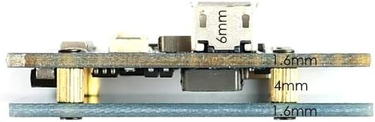
Image 3.1: Side profile of the F411-WING flight controller, illustrating its compact dimensions and mounting stack height.
4. Setup and Wiring
Proper setup and wiring are crucial for the safe and effective operation of your F411-WING Flight Controller. Always refer to the detailed wiring diagram and ensure all connections are secure before powering on.
4.1. Basic Connections
- Power Input: Connect your 2-6S LiPo battery to the designated power pads (6.5~30V). Observe polarity.
- ESCs: Connect your Electronic Speed Controllers (ESCs) to the motor outputs (M1, M2).
- Servos: Connect your servos to the S1-S5 servo outputs. Ensure correct voltage selection for Vx BEC.
- Receiver: Connect your receiver (e.g., SBUS, PPM) to the appropriate UART RX pad. SBUS input has a built-in inverter on UART1-RX.
- GPS/Compass: If using, connect to the I2C port (SDA, SCL) and a free UART for GPS data.
- Camera/VTX: Connect your FPV camera and video transmitter (VTX) to the designated pads for video input/output and power.
- Buzzer/LED Strip: Connect optional buzzer and WS2812 LED strip to their respective pads.
4.2. Wiring Diagram
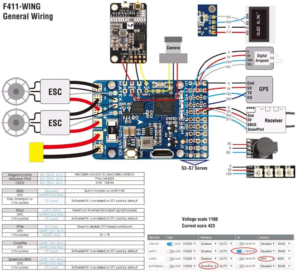
Image 4.1: Comprehensive wiring diagram for the F411-WING, illustrating connections for ESCs, servos, receiver, GPS, camera, and other peripherals.
4.3. Board Layout

Image 4.2: Detailed board layout of the F411-WING, highlighting key components, pads, and their functions.
4.4. Firmware Flashing
The F411-WING comes pre-flashed with INAV firmware. For updates or re-flashing:
- Download the latest INAV Configurator from the official INAV GitHub page.
- Connect the flight controller to your computer via a USB cable.
- Press and hold the DFU (Boot) button while plugging in the USB cable to enter DFU mode.
- In INAV Configurator, select the "Firmware Flasher" tab.
- Choose "MATEKF411" as the target and select the desired firmware version.
- Click "Load Firmware [Online]" and then "Flash Firmware".
- After flashing, disconnect and reconnect the FC. It should now appear as a COM port.

Image 4.3: The F411-WING flight controller connected via USB, with the blue status LED illuminated, indicating power and operation.
5. Operating Instructions
Once the flight controller is wired and configured in INAV Configurator, you are ready for operation.
5.1. Pre-Flight Checks
- Verify all connections are secure and correct.
- Ensure propellers are removed during initial setup and testing.
- Calibrate accelerometer and compass in INAV Configurator.
- Check motor direction and ESC calibration.
- Confirm control surface movements match transmitter inputs.
5.2. Flight Modes
INAV offers various flight modes. Configure these in the "Modes" tab of INAV Configurator and assign them to your transmitter switches:
- Manual Mode: Direct control of surfaces.
- Acro Mode: Rate mode, no self-leveling.
- Angle/Horizon Mode: Self-leveling modes.
- GPS Hold/Return to Home (RTH): Requires a GPS module for autonomous flight.
5.3. Arming and Disarming
Arming the flight controller activates the motors. Disarming stops them. Configure your arming switch in INAV Configurator. Always arm in a safe area with clear surroundings.
6. Maintenance
Regular maintenance ensures the longevity and reliability of your flight controller.
- Visual Inspection: Periodically check for loose wires, damaged components, or signs of overheating.
- Cleaning: Keep the board free from dust, dirt, and moisture. Use compressed air or a soft brush.
- Firmware Updates: Regularly check for and apply the latest INAV firmware updates to benefit from bug fixes and new features.
- Connection Integrity: Ensure all solder joints and connectors remain solid.
7. Troubleshooting
If you encounter issues, refer to the following common troubleshooting steps:
- No Power/LEDs Off:
- Check battery connection and voltage.
- Verify power input polarity.
- Inspect for short circuits.
- Cannot Connect to INAV Configurator:
- Ensure correct USB drivers are installed (e.g., STM32 Virtual COM Port Driver, Zadig for DFU mode).
- Try a different USB cable or port.
- Reboot your computer.
- Motors Not Arming:
- Check pre-arm safety features in INAV (e.g., accelerometer calibration, valid receiver input, no stick errors).
- Verify arming switch assignment in INAV.
- Ensure ESCs are calibrated.
- Incorrect Sensor Readings:
- Recalibrate accelerometer and compass.
- Check for vibrations affecting the IMU.
- Ensure the flight controller is mounted securely and correctly oriented.
8. Warranty and Support
This product is manufactured by Occus. For specific warranty information, please refer to the terms provided at the point of purchase or contact your retailer. General support for INAV firmware can be found on the official INAV project website and community forums.
For technical inquiries related to the Matek Systems F411-WING hardware, please contact the manufacturer or your authorized dealer.


