1. Introduction
The amiciSmart OVP4P-5A is a multi-functional three-phase protection device designed to safeguard electrical systems and connected equipment from various voltage anomalies. This intelligent relay provides comprehensive protection against overvoltage, undervoltage, phase loss, phase sequence errors, and phase unbalance. Equipped with an LCD display, it allows for real-time voltage monitoring, fault status indication, and easy parameter adjustment. This manual provides essential information for the safe installation, operation, and maintenance of your amiciSmart OVP4P-5A protection relay.
2. Safety Information
Please read and understand all safety instructions before installing or operating this device. Failure to follow these instructions may result in electric shock, fire, or serious injury.
- Qualified Personnel: Installation and maintenance must be performed by qualified electrical personnel only.
- Power Disconnection: Always disconnect power to the circuit before installing, wiring, or servicing the device.
- Proper Wiring: Ensure all wiring connections are secure and comply with local and national electrical codes.
- Environmental Conditions: Do not expose the device to moisture, extreme temperatures, or corrosive environments.
- Intended Use: Use the device only for its intended purpose as a three-phase voltage protection relay.
3. Product Overview
The amiciSmart OVP4P-5A features a compact design for DIN rail mounting and an intuitive LCD for monitoring and configuration.

Figure 3.1: Front view of the amiciSmart OVP4P-5A protection relay. This image displays the device's main body, the LCD screen, and the control buttons, along with the terminal connections at the top and bottom for phase inputs and relay outputs.
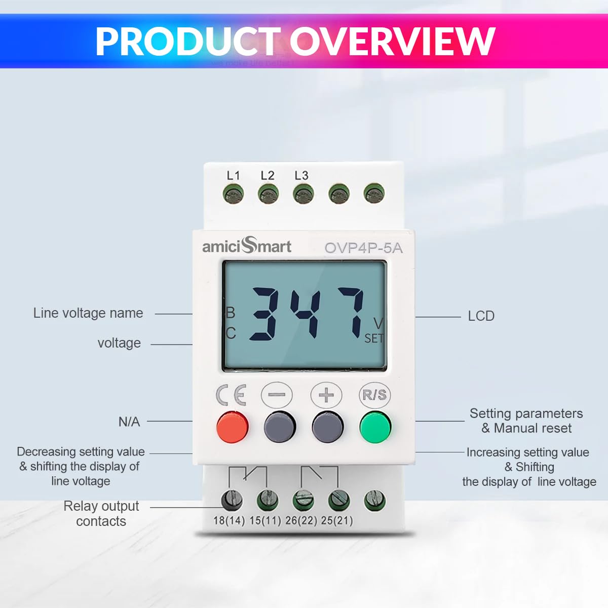
Figure 3.2: Labeled components of the amiciSmart OVP4P-5A. This diagram highlights the LCD display, the L1, L2, L3 phase input terminals, the control buttons (minus, plus, R/S), and the relay output contacts (18(14), 15(11), 26(22), 25(21)). The buttons are used for adjusting settings and navigating the display.
Key Features:
- Over Voltage Protection
- Under Voltage Protection
- Phase Loss Protection
- Phase Sequence Protection
- Phase Unbalance Protection
- Voltage Display (Real-time)
- Fault Records
- Adjustable protection parameters
- LCD display for monitoring and settings
- 35mm DIN rail mountable
4. Installation
The amiciSmart OVP4P-5A is designed for easy installation on a standard 35mm DIN rail. Ensure that the installation location is free from excessive vibration, moisture, and extreme temperatures.
4.1 Mounting
- Ensure all power to the installation site is disconnected and locked out.
- Hook the top clip of the device onto the DIN rail.
- Press the device downwards until it clicks securely onto the DIN rail.
4.2 Wiring
WARNING: All wiring must be performed by a qualified electrician in accordance with all applicable national and local electrical codes. Incorrect wiring can lead to device malfunction, damage, or severe injury.
The device requires a three-phase power supply connection and provides relay output contacts to control an external contactor or circuit breaker. The internal relay contacts are typically used to interrupt the control circuit of a main contactor, thereby disconnecting the load when a fault is detected.
- Connect the three-phase lines (L1, L2, L3) to the corresponding input terminals at the top of the device.
- Connect the neutral line (if applicable to your system, though this device primarily monitors phase-to-phase voltage) to the appropriate terminal if available or required by your system design.
- Connect the relay output contacts (e.g., 15(11) and 18(14) for normally open, or 15(11) and 26(22) for normally closed) to the control circuit of your external contactor. The specific terminals used will depend on whether you require a normally open (NO) or normally closed (NC) contact for your application.
- Ensure all connections are tight and secure.
Note: This device acts as a control signal for a main power contactor. It does not directly switch high-current loads. An appropriately rated external contactor must be used in conjunction with this protection relay.
5. Operation
Once installed and powered, the device will display the current phase voltage on its LCD screen. The device continuously monitors the three-phase supply for any deviations from the set parameters.

Figure 5.1: Multi-data display of the amiciSmart OVP4P-5A. The LCD cycles through various monitoring data, including Overvoltage Protection (OV), Undervoltage Protection (UV), Unbalance Protection (UB), and Phase Sequence Protection (SEQ). The 'SET' indicator shows when a parameter is being adjusted.
5.1 Display Modes
The LCD automatically cycles through different monitoring data, including:
- Current Line Voltage (e.g., L1-L2, L2-L3, L3-L1)
- Overvoltage (OV) setting
- Undervoltage (UV) setting
- Unbalance (UB) setting
- Phase Sequence (SEQ) status
5.2 Button Functions
- '-' Button: Decreases setting values, shifts the display of line voltage.
- '+' Button: Increases setting values, shifts the display of line voltage.
- 'R/S' Button: Used to enter parameter setting mode, confirm settings, and manually reset the device after a fault.
6. Parameter Settings
To adjust the protection parameters:
- Press and hold the 'R/S' button for approximately 3 seconds to enter the setting mode. The 'SET' indicator on the LCD will illuminate.
- Use the '+' or '-' buttons to navigate through the different parameters (e.g., OV, UV, UB, Delay Time).
- When the desired parameter is displayed, press the 'R/S' button briefly to select it for adjustment.
- Use the '+' or '-' buttons to change the value of the selected parameter.
- Press the 'R/S' button again to confirm the new value and move to the next parameter, or to exit the setting mode if all parameters have been adjusted.
- If no buttons are pressed for a certain period (typically 10-15 seconds) while in setting mode, the device may automatically exit without saving changes.
Adjustable Parameters:
- Overvoltage (OV) Range: 390V - 490V
- Undervoltage (UV) Range: 300V - 370V
- Voltage Hysteresis: 10V (fixed, for OV/UV)
- Overvoltage/Undervoltage Delay Time: 0.1s - 25s
- Three-phase Unbalanced Action Time: 1s - 25s
- Phase Loss Action Time: 1s
- Voltage Imbalance Range: 5% - 29%
7. Faults and Display Codes
When a fault condition is detected, the device will activate its protection mechanism (e.g., trip the external contactor) and display a corresponding fault code or status on the LCD. The device also stores fault records for diagnostic purposes.
- OV: Overvoltage detected.
- UV: Undervoltage detected.
- UB: Phase unbalance detected.
- SEQ: Incorrect phase sequence detected.
- Loss: Phase loss detected.
To clear a fault and reset the device, press the 'R/S' button briefly after the fault condition has been resolved.
8. Maintenance
The amiciSmart OVP4P-5A is designed for reliable operation with minimal maintenance. However, periodic checks are recommended to ensure optimal performance.
- Visual Inspection: Regularly inspect the device for any signs of physical damage, loose connections, or discoloration.
- Cleaning: Keep the device clean and free from dust and debris. Use a soft, dry cloth for cleaning. Do not use liquid cleaners.
- Connection Checks: Periodically verify that all wiring connections are secure and tight.
- Functionality Test: If possible and safe to do so, periodically test the protection functions by simulating fault conditions (e.g., temporarily reducing voltage) to ensure the relay trips as expected.
9. Troubleshooting
If the device is not functioning as expected, refer to the following troubleshooting guide:
| Problem | Possible Cause | Solution |
|---|---|---|
| Device does not power on | No power supply; Incorrect wiring; Blown fuse in circuit | Check power supply; Verify wiring connections; Check and replace circuit fuse if necessary. |
| Device trips frequently | Voltage fluctuations; Incorrect parameter settings; Actual fault condition | Monitor voltage stability; Adjust OV/UV/UB settings within safe limits; Investigate and resolve actual electrical system faults. |
| LCD display is blank or erratic | Power issue; Internal fault | Check power supply; Power cycle the device; If problem persists, contact support. |
| Cannot enter setting mode | Button not pressed long enough; Device locked | Press and hold 'R/S' button for at least 3 seconds; Check manual for any lock features (not specified for this model). |
If troubleshooting steps do not resolve the issue, please contact amiciSmart customer support for further assistance.
10. Technical Specifications
Refer to the following specifications for detailed information about the amiciSmart OVP4P-5A.

Figure 10.1: Product dimensions of the amiciSmart OVP4P-5A. The image shows the device with measurements: 4.2cm (width), 3.5cm (height from DIN rail), 5cm (depth), 8cm (total height), 4.4cm (top width), 1.8cm (top depth), 1.6cm (bottom depth). The device weighs 110g.
- Model: OVP4P-5A
- Overvoltage Adjustment Range: 390V - 490V
- Undervoltage Adjustment Range: 300V - 370V
- Voltage Hysteresis: 10V
- Delay Time for Overvoltage and Undervoltage: 0.1s - 25s
- Three-phase Unbalanced Action Time: 1s - 25s
- Phase Loss Action Time: 1s
- Voltage Imbalance Range: 5% - 29%
- Mounting: 35mm DIN Rail
- Dimensions (approx.): 9.9 x 7.8 x 5.2 cm
- Weight: 140 g
- Manufacturer: AA IMPORTERS LLC
- Country of Origin: China
11. Warranty and Support
For warranty information, technical support, or service inquiries, please refer to the purchase documentation or contact amiciSmart customer service. Keep your purchase receipt as proof of purchase.