1. Introduction
This manual provides detailed instructions for the installation, operation, maintenance, and troubleshooting of your ASRock B550 PRO4 motherboard. The ASRock B550 PRO4 is designed to support 3rd Generation AMD AM4 Ryzen processors and future AMD Ryzen processors, offering a robust platform for your computing needs.
Key features include an 8 Power Phase Design with Digi Power for stable power delivery, support for DDR4 memory up to 4733+ (OC), and multiple expansion slots including 1 PCIe 4.0 x16, 1 PCIe 3.0 x16, and 2 PCIe 3.0 x1. It also provides an M.2 Key E slot for WiFi modules and various graphics output options such as HDMI and D-Sub.
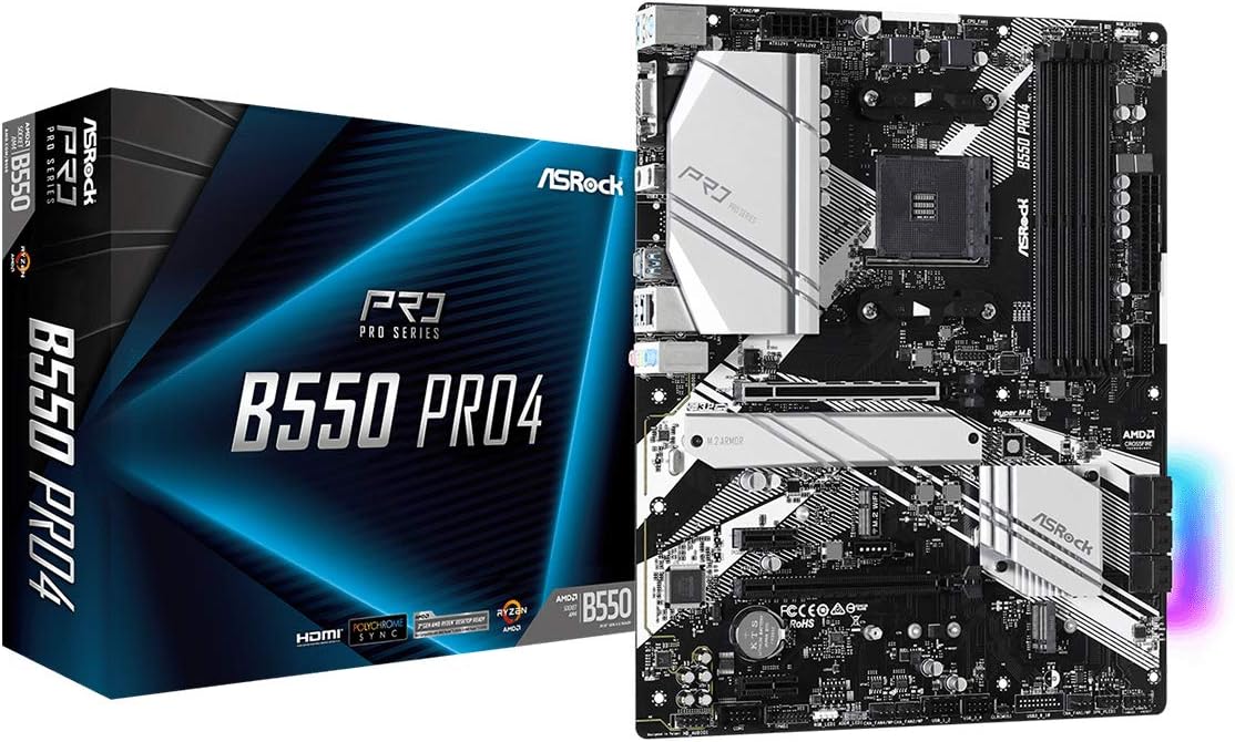
This image displays the ASRock B550 PRO4 motherboard alongside its retail box, highlighting the product's branding and overall appearance.
2. Setup and Installation
Before beginning installation, ensure your system is powered off and disconnected from the power source. Handle the motherboard by its edges to avoid static discharge.
2.1 Motherboard Layout
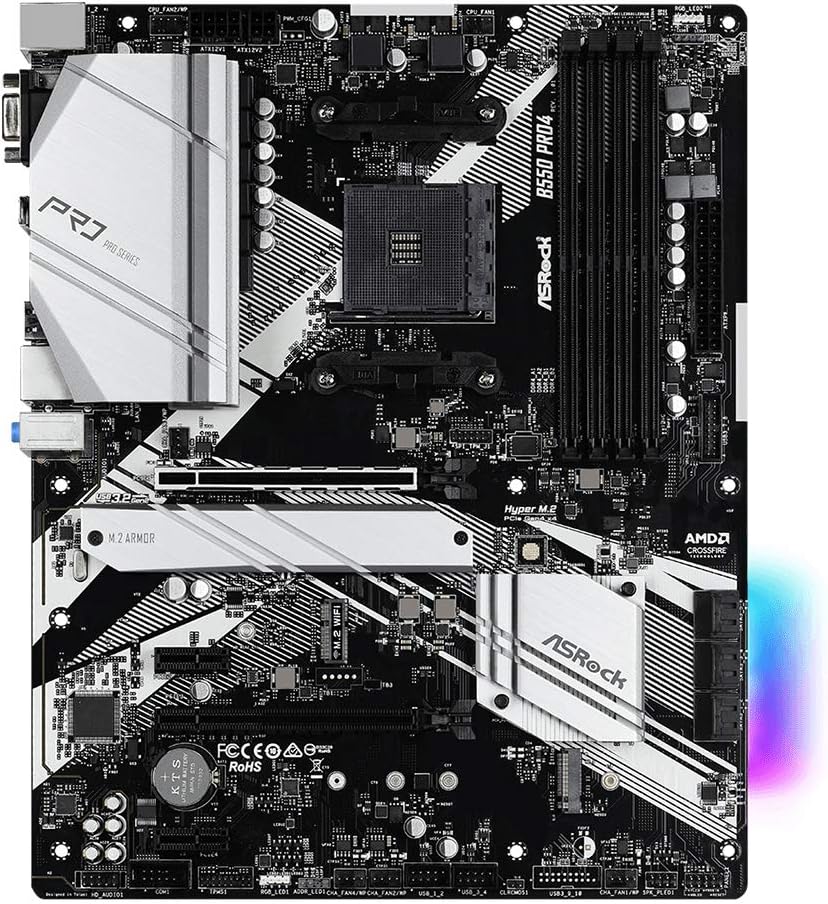
A comprehensive top-down view of the ASRock B550 PRO4 motherboard, illustrating the placement of the CPU socket, RAM slots, PCIe slots, M.2 slots, and various headers.
2.2 CPU Installation
- Open the CPU socket lever.
- Carefully align the triangular mark on your AMD AM4 processor with the mark on the socket.
- Gently place the CPU into the socket without forcing it.
- Close the socket lever to secure the CPU.
- Install the CPU cooler according to its manufacturer's instructions.
2.3 Memory (RAM) Installation
- Open the clips at both ends of the DDR4 memory slots.
- Align the notch on the DDR4 memory module with the key in the slot.
- Press down firmly on both ends of the memory module until the clips snap into place.
2.4 Storage Device Installation
- M.2 SSDs: Locate the M.2 slots on the motherboard. Remove the screw and standoff, insert the M.2 SSD at an angle, then push it down and secure with the screw.
- SATA Drives: Connect SATA data cables from your storage drives to the SATA ports on the motherboard. Connect power cables from your power supply to the drives.
2.5 Graphics Card and Expansion Cards
- Insert your graphics card into the primary PCIe 4.0 x16 slot. Ensure it is seated firmly and secured with the case latch or screw.
- Install any other expansion cards (e.g., sound cards, network cards) into the available PCIe slots.
2.6 Power Connections
- Connect the 24-pin ATX power connector from your power supply to the corresponding header on the motherboard.
- Connect the 8-pin (or 4+4-pin) CPU power connector to the ATX 12V power header.
2.7 Front Panel and I/O Connections
- Connect your case's front panel headers (power button, reset button, HDD LED, power LED) to the corresponding pins on the motherboard. Refer to the motherboard manual for exact pin layouts.
- Connect USB 2.0, USB 3.2 Gen1, and audio headers from your case to the motherboard.

This image provides a detailed view of the motherboard's rear I/O panel, featuring ports such as PS/2, USB 3.2 Gen1, HDMI, D-Sub, Ethernet, and audio jacks.
3. Operating the Motherboard
3.1 BIOS/UEFI Access
To access the BIOS/UEFI setup utility, power on your computer and repeatedly press the Del or F2 key during the boot process. This allows you to configure system settings, boot order, and hardware parameters.
3.2 Key Features
- PCIe 4.0 Support: The motherboard supports PCIe 4.0 for compatible graphics cards and NVMe SSDs, offering higher bandwidth compared to PCIe 3.0.
- DDR4 4733+ (OC): Utilize high-speed DDR4 memory modules with overclocking capabilities for enhanced system performance.
- Nahimic Audio: Experience immersive audio with Nahimic Audio technology, providing a vibrant and detailed listening experience across various output devices. The Sound Tracker feature offers a visual indicator of sound origins in games.

A visual representation of Nahimic Audio technology, emphasizing its ability to deliver an engaging and detailed listening experience for various audio outputs.
- Polychrome RGB: Customize your PC's aesthetic with Polychrome RGB. Connect compatible RGB LED strips to the motherboard's headers and synchronize lighting effects.

This image demonstrates the Polychrome RGB feature, allowing users to connect LED strips and customize lighting effects for a personalized PC aesthetic.
4. Maintenance
4.1 BIOS Updates
Regularly checking for and applying BIOS updates from the official ASRock website is recommended to ensure compatibility with new hardware (e.g., newer CPU generations) and to improve system stability. Follow the instructions provided by ASRock carefully during the update process.
4.2 Driver Updates
Keep your chipset, audio, network, and other device drivers updated to the latest versions available on the ASRock support page or from the component manufacturers. This ensures optimal performance and compatibility.
4.3 Physical Cleaning
Periodically clean dust from the motherboard and components using compressed air. Ensure the system is powered off and unplugged before cleaning. Avoid using liquids or abrasive materials.
5. Troubleshooting
5.1 System Not Booting
- Verify all power connections (24-pin ATX, 8-pin CPU) are securely seated.
- Ensure RAM modules are correctly installed in their slots. Try reseating them or testing with one module at a time.
- Check that the CPU cooler is properly installed and its fan is spinning.
- Confirm the graphics card is fully seated in its PCIe slot and any required PCIe power cables are connected.
5.2 Ryzen 5000 Series CPU Compatibility
If you are using a Ryzen 5000 series processor, a BIOS update may be required for proper functionality. The motherboard might ship with an older BIOS version that does not fully support these newer CPUs. Refer to the ASRock website for the latest compatible BIOS version and update instructions. In some cases, an older, compatible CPU might be needed to perform the initial BIOS flash.
5.3 XMP Profile Issues
If enabling XMP (Extreme Memory Profile) in the BIOS leads to boot failures or a black screen, you may need to clear the CMOS. To do this, power off the system, unplug it, and locate the CMOS clear jumper (usually labeled CLRCMOS1) on the motherboard. Short the pins for about 10 seconds using a metal object like a screwdriver or paperclip, then remove the short and restart the system. Alternatively, removing the CMOS battery for a few minutes can also clear the settings.
5.4 USB 3.0 Front Panel Header
Exercise caution when connecting the USB 3.0 front panel header cable, as the pins can be delicate. Ensure proper alignment before applying gentle, even pressure to avoid bending or breaking pins.
6. Specifications
| Feature | Specification |
|---|---|
| Brand | ASRock |
| Model Name | B550 PRO4 |
| CPU Socket | Socket AM4 |
| Compatible Processors | AMD Ryzen 3rd Generation / Future AMD Ryzen Processors |
| Chipset Type | AMD B550 |
| RAM Memory Technology | DDR4 |
| Memory Speed | 2400 MHz (Supports up to 4733+ MHz OC) |
| PCIe Slots | 1 x PCIe 4.0 x16, 1 x PCIe 3.0 x16, 2 x PCIe 3.0 x1 |
| M.2 Slots | 2 (1 x PCIe 4.0 x4, 1 x PCIe 3.0 x4/SATA), 1 x M.2 Key E for WiFi |
| Graphics Output Options | HDMI, D-Sub |
| USB 2.0 Ports | 1 (internal header) |
| Product Dimensions | 14.8 x 13 x 3.5 inches |
| Item Weight | 2.2 pounds |
7. Warranty and Support
ASRock provides a manufacturer's warranty for its products. For specific warranty terms and conditions, including details on pin damage repair, please refer to the official ASRock website or your regional ASRock support documentation. It is recommended to retain your proof of purchase for warranty claims.

An image detailing ASRock's 2-year product warranty. The text, primarily in Japanese, indicates a 2-year manufacturer warranty and free repair for bent pins within 3 months of purchase, provided the product is from an authorized reseller and proof of purchase is available.
For further assistance, driver downloads, BIOS updates, and technical support, please visit the official ASRock website or contact ASRock customer service. You can also visit the ASRock Store on Amazon for product information.


