1. Product Overview
This manual provides instructions for the L-faster MY1020 500W Motor Kit, specifically the 36V Pedal Kit variant, designed for 4-wheel child go-karts. This kit enables chain drive speed control via a foot pedal accelerator, offering a complete solution for electric go-kart conversion or assembly.
1.1 Package Contents
The L-faster MY1020 500W Motor Kit (36V Pedal Kit) includes the following components:
- 1 x 500W Brush Motor (MY1020)
- 1 x Motor Controller (with fuse wire)
- 1 x Pedal Throttle
- 1 x Key Switch (with voltmeter)
- 1 x No-teeth Freewheel
- 1 x Chain Wheel (55 teeth)
- 1 x 25H Chain (106 links)
- 1 x Freewheel Adapter (27mm)
- 1 x Brake Sensor
- 1 x T8F Chain Sprocket 11 teeth (gift)
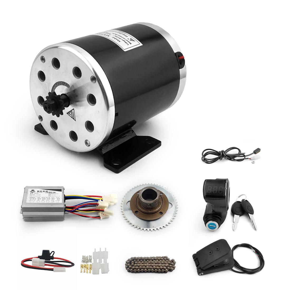
Image 1.1: All components of the L-faster MY1020 500W Motor Kit (36V Pedal Kit).
Video 1.1: Overview of the MY1020 motor kit components and initial connections.
2. Safety Information
Read all instructions carefully before installation and operation. Failure to follow safety guidelines may result in property damage or personal injury.
- Always disconnect power before performing any maintenance or installation.
- Ensure all electrical connections are secure and properly insulated to prevent short circuits.
- Wear appropriate personal protective equipment (PPE) during installation.
- This kit is intended for use with 36V battery systems only. Using an incorrect voltage may damage components.
- Keep children and unauthorized personnel away from the work area during installation.
3. Components Overview
3.1 Motor Controller
The motor controller manages power delivery to the motor based on throttle input and other sensor data. It includes a fuse for overcurrent protection.

Image 3.1: Motor controller showing various input/output connections.

Image 3.2: Dimensions of the motor controller.
3.2 Pedal Throttle
The foot pedal throttle provides variable speed control for the go-kart.

Image 3.3: Dimensions of the pedal throttle.
3.3 Key Switch with Voltmeter
This component serves as the main power switch and displays the battery voltage.

Image 3.4: Key switch with voltmeter.
3.4 MY1020 500W Brush Motor
The core of the drive system, providing 500W of power for the go-kart.

Image 3.5: Technical drawing and data for the MY1020 motor.
3.5 Drive Train Components
Includes the chain wheel, no-teeth freewheel, freewheel adapter, and 25H chain for power transmission.

Image 3.6: Chain wheel, freewheel, freewheel adapter, and 25H chain.
4. Setup and Installation
Proper installation is crucial for the safe and efficient operation of your go-kart. Refer to the wiring diagram below for connection details.
4.1 Wiring Diagram

Image 4.1: Wiring diagram for the L-faster MY1020 500W Motor Kit.
4.2 Installation Steps
- Mount the Motor: Securely attach the MY1020 motor to the go-kart frame using appropriate hardware. Ensure proper alignment for the chain drive.
- Install Drive Train: Mount the no-teeth freewheel and freewheel adapter onto the go-kart axle. Install the 55-tooth chain wheel. Connect the 25H chain, ensuring correct tension.
- Connect Motor to Controller: Connect the motor wires to the corresponding motor output terminals on the controller.
- Connect Battery: Connect your 36V battery pack to the battery input terminals on the controller. Ensure correct polarity (red to positive, black to negative).
- Install Key Switch: Mount the key switch with voltmeter in an accessible location. Connect its wires to the controller's power lock input.
- Install Pedal Throttle: Mount the pedal throttle in a comfortable position for the operator. Connect its wires to the controller's throttle input.
- Install Brake Sensor: Attach the brake sensor to the brake lever mechanism. Connect its wires to the controller's brake input.
- Optional Connections: If applicable, connect the brake light and general light wires to the controller.
- Final Check: Double-check all connections for security and correct wiring according to the diagram. Ensure no loose wires or potential short circuits.
5. Operating Instructions
- Power On: Insert the key into the key switch and turn it to the 'ON' position. The voltmeter display will show the current battery voltage.
- Start Operation: Gently press the foot pedal throttle to engage the motor and begin movement. The speed will increase as the pedal is pressed further.
- Braking: Apply the go-kart's brake. The brake sensor will signal the controller to cut power to the motor, allowing the brakes to function effectively.
- Power Off: To stop operation, release the throttle and turn the key switch to the 'OFF' position. Remove the key for security.
6. Maintenance
Regular maintenance ensures the longevity and optimal performance of your motor kit.
- Chain Lubrication: Periodically lubricate the drive chain to reduce wear and ensure smooth operation.
- Electrical Connections: Inspect all electrical connections regularly for corrosion or looseness. Tighten as necessary.
- Motor Inspection: Check the motor for any unusual noises, excessive heat, or physical damage.
- Battery Care: Follow the manufacturer's guidelines for battery charging and storage to maximize battery life.
- Component Cleaning: Keep all components clean and free from dirt, dust, and moisture.
7. Troubleshooting
Refer to the table below for common issues and their potential solutions.
| Problem | Possible Cause | Solution |
|---|---|---|
| Motor does not run | No power to controller; Loose connections; Faulty key switch; Low battery voltage | Check battery charge; Verify all connections; Test key switch; Check fuse on controller. |
| Inconsistent speed control | Faulty pedal throttle; Loose throttle connection | Inspect throttle wiring; Replace throttle if necessary. |
| Motor runs but no power to wheels | Chain disengaged or broken; Freewheel issue | Re-engage or replace chain; Inspect freewheel and adapter. |
| Voltmeter shows incorrect reading | Loose connection to voltmeter; Faulty voltmeter | Check wiring to key switch; Replace key switch assembly. |
8. Specifications
Technical specifications for the L-faster MY1020 500W Motor Kit (36V Pedal Kit).
| Feature | Specification |
|---|---|
| Brand | L-faster |
| Motor Model | MY1020 |
| Rated Output Power | 500W |
| Rated Voltage | 36V DC |
| Rated Speed | 2500 RPM |
| No Load Speed | 3150 RPM |
| Full Load Current | 17.8 A |
| No Load Current | 2.2 A |
| Rated Torque | 1.9 N.m |
| Efficiency | ≥78% |
| Application | Light E.V. / E-scooter |
| Assembly Required | Yes |
| Manufacturer Part Number | YK-B-797 |
9. Warranty and Support
For warranty information and technical support, please refer to the product listing on Amazon or contact the seller directly. Keep your purchase receipt as proof of purchase.
Seller: l-faster