
1. Introduction
This document provides detailed instructions for the Electronics-Salon 4 DPDT Signal Relay Module Board, DC 5V version. This module is designed for various electronic projects, including those involving microcontrollers such as Arduino, Raspberry Pi, 8051, and PIC. It features four Double Pole Double Throw (DPDT) signal relays, offering reliable switching capabilities for low-power applications.
The module incorporates TAKAMISAWA RY5W-K high-quality relays with gold overlay silver-palladium switch contacts, ensuring durability and performance. Darlington transistor circuits drive each relay coil, complemented by an LED indicator for each channel to show its activation status.
2. Features
- Four DPDT signal relays (TAKAMISAWA RY5W-K).
- High-quality gold overlay silver-palladium switch contact material.
- Darlington transistor drive circuits for relay coils.
- Individual LED indicators for each relay channel.
- High-quality screw terminal blocks for secure connections.
- FR-4 fiber glass PCB with dual copper layers for enhanced durability.
3. Setup and Connections
This section details the necessary connections for powering and controlling the relay module.
3.1 Power Supply Connection
Connect the module to a DC 5V power source using the VCC and GND terminals on the input side. The module operates within a voltage range of 3.6V to 6.5V DC. Ensure the power supply can provide at least 200mA at 5V DC for stable operation when all relays are active.
- VCC: Connect to the positive (+) terminal of your 5V DC power supply.
- GND: Connect to the negative (-) terminal of your 5V DC power supply.
3.2 Control Signal Connections
Each relay channel (IN-A, IN-B, IN-C, IN-D) is controlled by a separate digital input signal. These inputs are compatible with common microcontroller logic levels.
- IN-A, IN-B, IN-C, IN-D: Connect these terminals to the digital output pins of your microcontroller (e.g., Arduino, Raspberry Pi).
- Control Signal Voltage:
- Low Level (0V - 0.5V DC): The corresponding relay will not activate.
- High Level (2.5V - 24V DC): The corresponding relay will activate.
3.3 Output Connections (Relay Contacts)
Each DPDT relay provides two sets of contacts: Normally Open (NO), Normally Closed (NC), and Common (C). These contacts are isolated from the control circuitry and can switch independent loads.
- NOx: Normally Open contact for relay X. This contact is open when the relay is de-energized and closes when the relay is activated.
- NCx: Normally Closed contact for relay X. This contact is closed when the relay is de-energized and opens when the relay is activated.
- Cx: Common contact for relay X. This is the pivot point for the switch.
Output Contact Ratings:
- AC Loads: Up to 120V AC / 0.5 Amp per switch.
- DC Loads: Up to 24V DC / 1.0 Amp per switch.
Ensure that the loads connected to the relay contacts do not exceed these specified ratings to prevent damage to the module or connected devices.
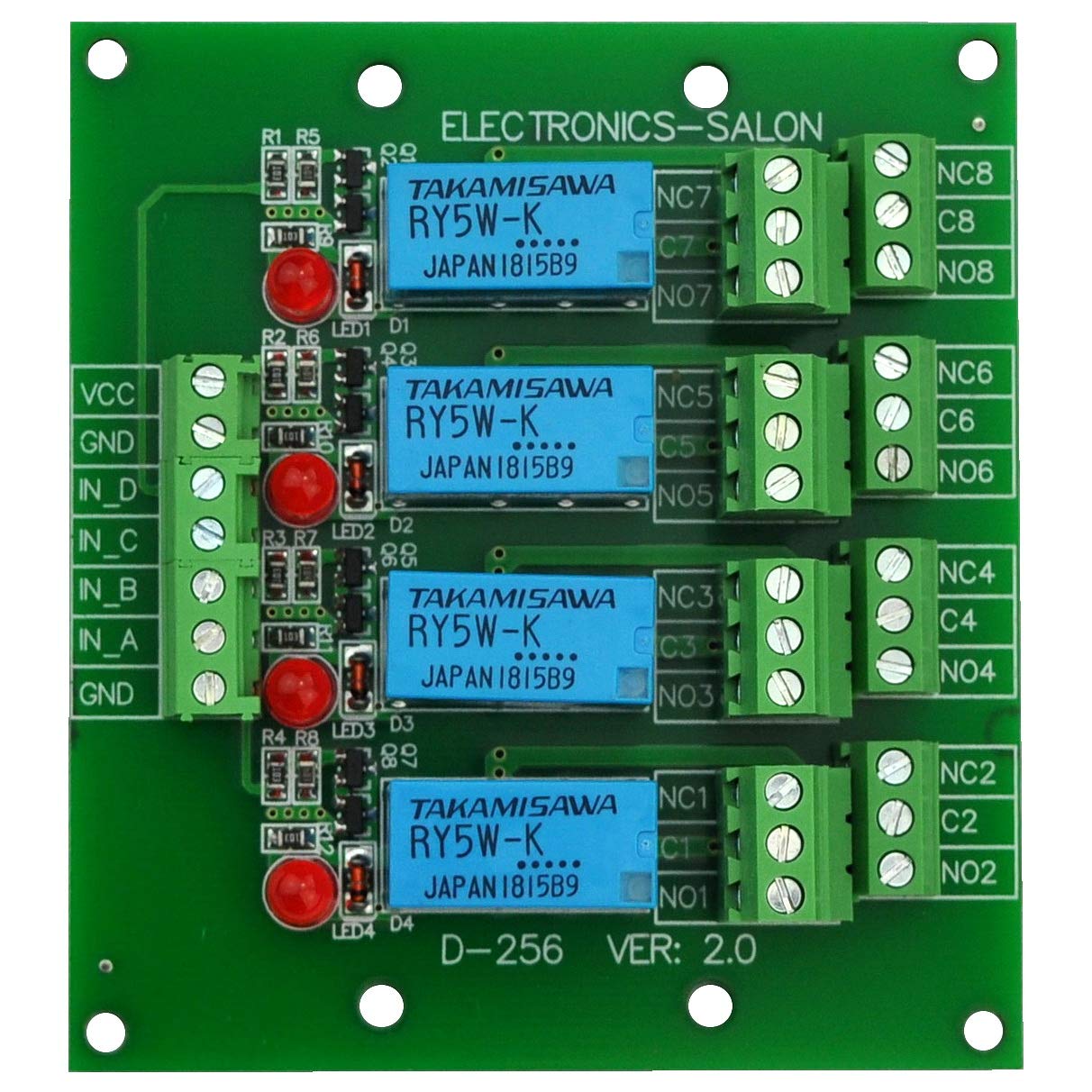
Figure 1: Top-down view of the 4 DPDT Signal Relay Module Board. This image shows the layout of the relays, LED indicators, input screw terminals (VCC, GND, IN-A, IN-B, IN-C, IN-D), and output screw terminals (NOx, Cx, NCx for each relay).
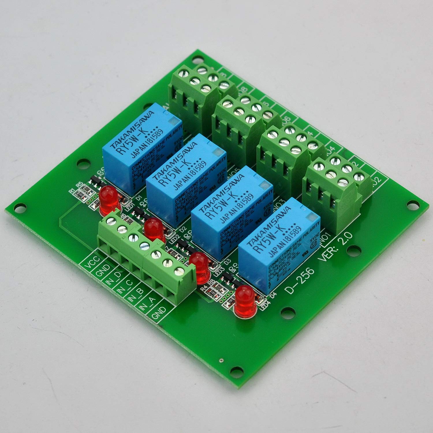
Figure 2: Angled view of the relay module, highlighting the input power and control signal screw terminals on the left, and the output relay contact screw terminals on the right. This perspective helps in identifying connection points.
4. Operating Instructions
To operate the relay module, apply the appropriate control signal to the IN-X pins. Each relay operates independently.
- Power On: Connect the 5V DC power supply to the VCC and GND terminals. The module will be powered, but relays will remain in their de-energized state (NC contacts closed, NO contacts open).
- Activate a Relay: To activate a specific relay (e.g., Relay A), apply a high-level signal (2.5V to 24V DC) to its corresponding input pin (IN-A). The LED indicator for that relay will illuminate, and the relay contacts will switch (NC opens, NO closes).
- Deactivate a Relay: To deactivate a relay, remove the high-level signal or apply a low-level signal (0V to 0.5V DC) to its input pin. The LED indicator will turn off, and the relay contacts will return to their de-energized state (NC closes, NO opens).
- Multiple Relays: Each relay can be controlled independently by its respective IN-X pin.
For detailed wiring and circuit understanding, refer to the schematic diagram provided in Section 6.
5. Specifications
| Parameter | Value |
|---|---|
| Model Number | HM-38865 |
| Operating Voltage (VCC) | 3.6V to 6.5V DC |
| Operating Current (at 5VDC) | 200mA (max, all relays active) |
| Control Signal Voltage (Low Level) | 0V - 0.5V DC (Relay OFF) |
| Control Signal Voltage (High Level) | 2.5V - 24V DC (Relay ON) |
| Relay Type | 4 x DPDT Signal Relays (TAKAMISAWA RY5W-K) |
| Contact Material | Gold Overlay Silver-palladium |
| AC Contact Rating | 120V AC / 0.5 Amp per switch |
| DC Contact Rating | 24V DC / 1.0 Amp per switch |
| PCB Material | FR-4 Fiber Glass, Dual Copper Layers |
| Dimensions (L x W x H) | 72.5mm x 80mm x 18.1mm (approx.) |
| Connector Type | Screw Terminals |
6. Schematic Diagram
The following schematic illustrates the internal circuitry and connections of the 4 DPDT Signal Relay Module. It shows the power supply, control signal inputs, Darlington transistor drive circuits, LED indicators, and relay contact configurations.

Figure 3: Schematic diagram detailing the connections for power (VCC, GND), input control signals (IN_A, IN_B, etc.), and output relay contacts (NO, C, NC). Each channel includes a Darlington transistor driver and an LED indicator.
7. Dimensions
Refer to the diagram below for the physical dimensions and mounting hole locations of the relay module board.

Figure 4: Dimensional drawing showing the top and side views of the module, including overall length (72.5mm), width (80mm), height (18.1mm), and the diameter of the four mounting holes (3.2mm).
8. Maintenance
The Electronics-Salon 4 DPDT Signal Relay Module is designed for reliable operation with minimal maintenance. Follow these guidelines to ensure longevity:
- Environmental Conditions: Operate the module within a clean, dry environment, free from excessive dust, moisture, and corrosive gases.
- Power Supply: Ensure the power supply voltage remains within the specified range (3.6V to 6.5V DC). Over-voltage can damage components.
- Load Ratings: Do not exceed the maximum current and voltage ratings for the relay contacts. Overloading can lead to premature relay failure.
- Connections: Periodically check screw terminal connections to ensure they are secure. Loose connections can cause intermittent operation or arcing.
- Cleaning: If necessary, gently clean the board with a soft, dry brush or compressed air to remove dust. Avoid using liquids or solvents.
9. Troubleshooting
If you encounter issues with the relay module, consider the following troubleshooting steps:
- Relay Not Activating:
- Verify the power supply (VCC and GND) is correctly connected and providing 5V DC.
- Check if the control signal to the IN-X pin is a high-level signal (2.5V - 24V DC).
- Ensure the LED indicator for the specific relay is illuminating when the control signal is applied. If not, check the control signal source.
- Inspect the screw terminal connections for looseness or incorrect wiring.
- Relay Always On/Off:
- Confirm the control signal is correctly switching between high and low levels. A floating input might cause erratic behavior.
- Check for any short circuits on the control input pins.
- Load Not Switching:
- Verify that the relay is activating (LED on, audible click).
- Check the wiring to the NO/NC/C contacts of the relay. Ensure the load is correctly connected to the desired contact type (NO or NC) and the common (C) terminal.
- Confirm the load's voltage and current requirements do not exceed the relay's contact ratings (120V AC / 0.5A or 24V DC / 1.0A).
- Test the load independently to ensure it is functional.
- Module Overheating:
- Ensure the power supply voltage is not too high.
- Verify that the total current draw from the power supply does not exceed its capacity.
- Check for any short circuits on the board or connected loads.
10. Additional Resources
For further technical details and comprehensive information, please refer to the official datasheet:
11. Warranty and Support
This product is manufactured by Electronics-Salon. For any technical support, warranty inquiries, or assistance with product operation, please contact the manufacturer directly through their official channels or the retailer from whom the product was purchased.
Please retain your proof of purchase for warranty claims.