1. Introduction
The Tilswall FY8233X is a portable, battery-powered digital multimeter designed for measuring AC/DC voltage, AC/DC current, resistance, capacitance, frequency, diode, continuity, non-contact voltage (NCV), and live wire detection. This manual provides essential information for safe and effective operation of the device.
2. Safety Information
Please read and understand all safety warnings and operating instructions before using this multimeter. Failure to do so may result in injury or damage to the meter or equipment under test.
- This device is rated for CAT III 600V, ensuring high security for various electrical applications.
- The multimeter features double protection and anti-burn design, including an explosion-proof ceramic fuse, to protect against overloads across all ranges.
- Always ensure the test leads are correctly inserted into the input jacks for the desired measurement.
- Do not attempt to measure voltage or current exceeding the specified maximum limits.
- Verify the meter's functionality on a known voltage source before use.
- The product complies with CE and RoHS standards.

Image: The Tilswall Digital Multimeter highlighting its CAT III 600V rating and CE/RoHS certifications, along with safety fuses, indicating robust safety features for electrical measurements.

Image: An exploded view of the Tilswall Digital Multimeter, illustrating its internal components, including the circuit board and explosion-proof ceramic fuses, which provide double protection and anti-burn capabilities across all measurement ranges.
3. Product Overview
The Tilswall FY8233X Digital Multimeter features a clear LCD display, a rotary switch for function selection, and multiple input jacks for test leads. It is designed for ease of use and accurate readings.
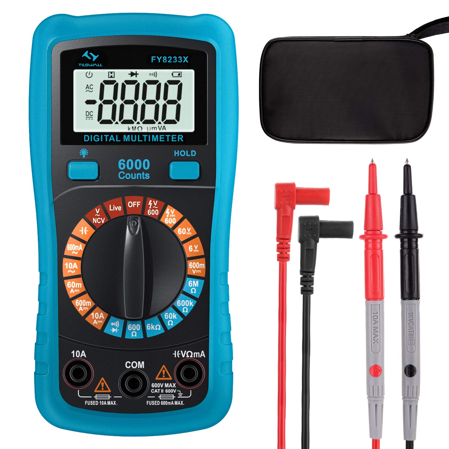
Image: The Tilswall FY8233X Digital Multimeter, displaying its 6000 counts LCD screen, central rotary switch with various measurement functions (Capacitance, AC/DC Current, Resistance, Continuity, AC/DC Voltage, Diode, NCV, Live, Battery), and input terminals.
Key Components:
- LCD Display: Shows measurement readings, units, and function indicators.
- Rotary Switch: Used to select the desired measurement function.
- Input Jacks:
- COM: Common (negative) input jack for all measurements.
- VΩmA: Positive input jack for voltage, resistance, capacitance, diode, continuity, and small current measurements.
- 10A: Positive input jack for large current (up to 10A) measurements.
- Function Buttons: Such as HOLD for data hold, backlight, and range selection.
4. Setup
Battery Installation:
The Tilswall FY8233X is battery-powered. Before first use, or when the low battery indicator appears, install or replace the batteries.
- Ensure the multimeter is turned OFF.
- Locate the battery compartment cover on the back of the meter.
- Use a screwdriver to remove the screw securing the cover.
- Carefully remove the cover.
- Insert new batteries, observing the correct polarity (+ and -).
- Replace the battery compartment cover and secure it with the screw.
5. Operating Instructions
Always connect the black test lead to the COM jack and the red test lead to the appropriate positive input jack (VΩmA or 10A) for the desired measurement.
5.1. AC/DC Voltage Measurement
- Turn the rotary switch to the 'V~' (AC Voltage) or 'V=' (DC Voltage) position.
- Connect the red test lead to the VΩmA jack and the black test lead to the COM jack.
- Touch the test probes to the circuit points where voltage is to be measured (in parallel with the load).
- Read the voltage value on the display. The sample speed is 3 times per second for accurate data.

Image: The Tilswall Digital Multimeter demonstrating battery voltage measurement (1.5V) and AC voltage measurement from a power strip (235V), illustrating its capability to measure both DC and AC voltages with a sample speed of 3 times per second.
5.2. AC/DC Current Measurement
- Turn the rotary switch to the 'A~' (AC Current) or 'A=' (DC Current) position.
- For currents up to 600mA, connect the red test lead to the VΩmA jack. For currents up to 10A, connect the red test lead to the 10A jack. Connect the black test lead to the COM jack.
- Open the circuit and connect the multimeter in series with the load.
- Read the current value on the display.
5.3. Resistance Measurement
- Turn the rotary switch to the 'Ω' (Resistance) position.
- Connect the red test lead to the VΩmA jack and the black test lead to the COM jack.
- Ensure the circuit is de-energized. Touch the test probes across the component to measure its resistance.
- Read the resistance value on the display.
5.4. Continuity Test
- Turn the rotary switch to the '•)))' (Continuity) position.
- Connect the red test lead to the VΩmA jack and the black test lead to the COM jack.
- Ensure the circuit is de-energized. Touch the test probes across the component or wire.
- If the resistance is below a certain threshold (typically 50Ω), the buzzer will sound, indicating continuity.
5.5. Diode Test
- Turn the rotary switch to the '→|' (Diode) position.
- Connect the red test lead to the VΩmA jack and the black test lead to the COM jack.
- Ensure the circuit is de-energized. Touch the red probe to the anode and the black probe to the cathode of the diode.
- Read the forward voltage drop on the display. Reverse the probes; an open circuit reading indicates a good diode.
5.6. Capacitance Measurement
- Turn the rotary switch to the '╂╂' (Capacitance) position.
- Connect the red test lead to the VΩmA jack and the black test lead to the COM jack.
- Ensure the capacitor is fully discharged before testing. Touch the test probes across the capacitor terminals.
- Read the capacitance value on the display.
5.7. Non-Contact Voltage (NCV) Function
- Turn the rotary switch to the 'NCV' position.
- Move the top end of the multimeter near the conductor or outlet to be tested.
- The meter will emit an audible and visual alarm (beeping and flashing LED) if AC voltage is detected, indicating the presence of live voltage without direct contact.

Image: The Tilswall Digital Multimeter performing a Non-Contact Voltage (NCV) test near an electrical panel, showing the display indicating voltage detection and a voice reminder icon, demonstrating its safe and convenient method for detecting live wires.
5.8. Live Wire Detection
- Turn the rotary switch to the 'Live' position.
- Connect the red test lead to the VΩmA jack and leave the black test lead disconnected or in the COM jack.
- Touch the red probe to the suspected live wire or terminal.
- The meter will indicate the presence of a live wire through an audible and visual alarm.
5.9. General Usage Example

Image: A person using the Tilswall Digital Multimeter with its test leads to measure components on a circuit board, demonstrating a typical application for electronic troubleshooting and repair.
6. Maintenance
6.1. Cleaning:
Wipe the meter with a damp cloth and mild detergent. Do not use abrasives or solvents. Ensure the meter is dry before use.
6.2. Battery Replacement:
Refer to the 'Battery Installation' section (Section 4) for instructions on replacing the batteries when the low battery indicator appears on the display.
6.3. Fuse Replacement:
If the current measurement function fails, the fuse may need replacement. This should only be performed by qualified personnel. Use only fuses of the specified type and rating (e.g., explosion-proof ceramic fuse).
7. Troubleshooting
- No Display: Check battery installation and charge. Replace batteries if necessary.
- Incorrect Readings: Ensure test leads are correctly inserted, the rotary switch is on the correct function, and the circuit is properly connected. Check for damaged test leads.
- Current Measurement Failure: Check the fuse. If blown, replace with a fuse of the correct rating.
- NCV/Live Detection Not Working: Ensure the function is selected and the meter is held close enough to the live source.
8. Specifications
| Specification | Value |
|---|---|
| Brand | Tilswall |
| Model | FY8233X |
| Power Source | Battery Powered |
| Style | Digital |
| Item Dimensions (L x W x H) | 17 x 11.5 x 6 Centimeters |
| Safety Standard | CE, CAT III 600V |
| Measurement Type | Multimeter (Voltage, Current, Resistance, Capacitance, Diode, Continuity, NCV, Live) |
| UPC | 779186690885 |
9. Warranty and Support
For warranty information or technical support, please contact Tilswall customer service through their official website or the retailer from whom the product was purchased. Please have your product model (FY8233X) and purchase details ready when contacting support.