Introduction
This manual provides comprehensive instructions for the installation, operation, and maintenance of your FLORADIS Hydraulic Adjustable Automatic Door Closer. Designed for residential and commercial light-to-medium doors, this device ensures controlled door closure and offers a convenient hold-open function. Please read these instructions carefully before installation and use to ensure proper function and safety.
Safety Information
- Ensure all components are securely fastened to prevent injury or damage.
- Do not attempt to modify the door closer or its internal hydraulic mechanism.
- Keep hands and fingers clear of moving parts during operation and adjustment.
- If you are unsure about any installation or adjustment step, consult a qualified professional.
Package Contents
Please verify that all items listed below are included in your package:

Image: The image displays the FLORADIS Automatic Door Closer, including the main body, arm assembly, parallel plate, mounting templates, installation instructions, and a bonus magnetic door stopper, all within its retail packaging.
- Automatic Door Closer Main Body
- Arm Assembly (Connecting Rod, Telescopic Rocker, Shaft)
- Parallel Installation Plate
- Mounting Templates
- Installation Instructions
- Screws and Washers
- Bonus Magnetic Door Stopper
Product Components Overview
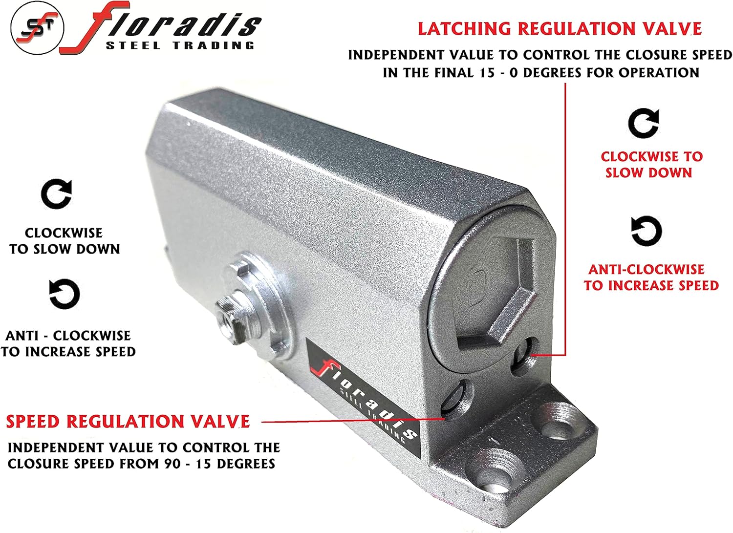
Image: A detailed diagram illustrating the various components of the door closer, including the main body, shaft, connecting rod, telescopic rocker, rocker bracket, control screw, and dust cover. Insets show the aluminum alloy case, high torsion alloy spring, connecting rod shaft, and stable rivets.
The FLORADIS Automatic Door Closer consists of several key parts:
- Main Body: Contains the hydraulic mechanism for controlled closing.
- Shaft: Connects the main body to the arm assembly.
- Connecting Rod: Part of the arm assembly, linking the shaft to the telescopic rocker.
- Telescopic Rocker: An adjustable arm component that connects to the door frame or door.
- Rocker Bracket: Secures the telescopic rocker to the mounting surface.
- Control Screw: Used for fine-tuning adjustments.
- Dust Cover: Protects internal components from environmental elements.
- Aluminum Alloy Case: Durable exterior housing providing protection and structural integrity.
- High Torsion Alloy Spring: Provides the necessary force for door closure.
- Stable Rivets: Ensure secure and lasting connections between components.
Installation
General Guidelines
The FLORADIS Automatic Door Closer can be installed in various configurations depending on your door type and opening direction. Always refer to the provided mounting templates for precise hole placement and ensure the door closer is level.
Installation Types
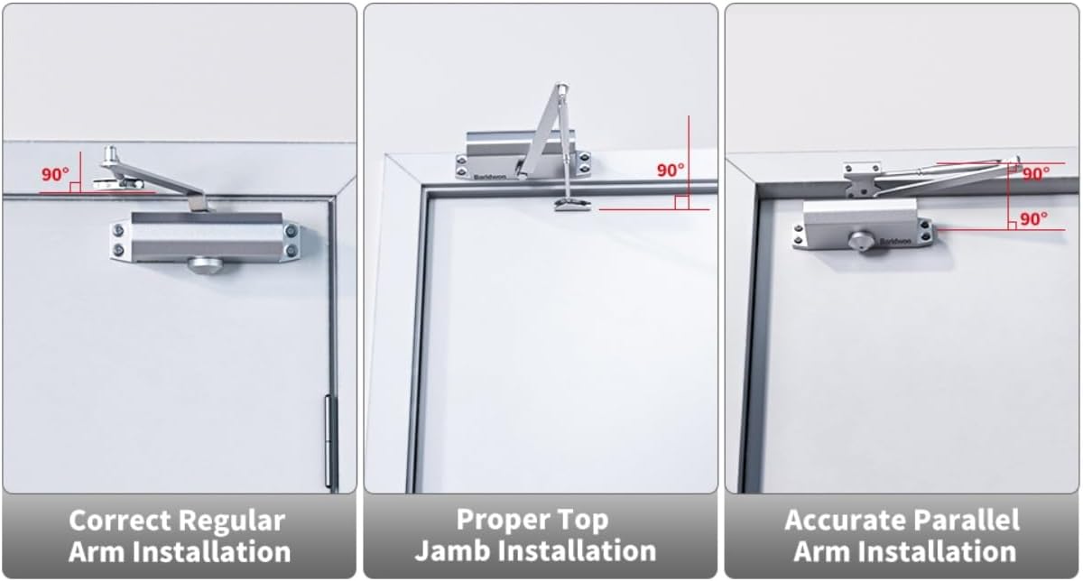
Image: Three diagrams illustrating different door closer installation methods: Correct Regular Arm Installation, Proper Top Jamb Installation, and Accurate Parallel Arm Installation, showing the angle of the arm relative to the door and frame.
- Regular Arm Installation: The closer body is mounted on the pull side of the door, and the arm extends away from the door.
- Top Jamb Installation: The closer body is mounted on the push side of the door frame, and the arm extends over the door.
- Parallel Arm Installation: The closer body is mounted on the push side of the door, and the arm is parallel to the door frame when closed. This configuration requires the parallel installation plate.
Parallel Plate Usage

Image: A diagram explaining when to use the parallel plate. It shows that if the door and frame are on the same plane, standard installation is used. If there is a gap of 1.97 inches or more between the door and frame, the parallel plate is required for parallel arm installation.
The parallel installation plate is necessary for parallel arm installations, especially when there is a significant gap (1.97 inches or more) between the door and the door frame. This plate ensures proper alignment and function of the door closer in such scenarios.
Step-by-Step Installation (General)
- Prepare the Door and Frame: Determine the desired installation type (Regular, Top Jamb, or Parallel). Use the provided mounting template to mark the drilling locations on the door and/or door frame.
- Drill Pilot Holes: Drill pilot holes at the marked locations. Ensure the holes are appropriate for the provided screws.
- Mount the Main Body: Secure the main door closer body to the door or frame using the screws. For parallel arm installation, first secure the parallel plate to the door frame.
- Attach the Arm Assembly: Connect the arm assembly to the closer's shaft and the door frame/door. Ensure all connections are tight.
- Adjust Arm Length: Adjust the telescopic rocker to achieve the correct arm length and angle as per your chosen installation type.
- Test Operation: Open and close the door manually to ensure smooth movement and proper alignment before making final adjustments.
Operating and Adjusting
Hold Open Function
This door closer features a hold-open function. When the door is opened beyond 90 degrees (up to 180 degrees), it will remain open at the desired angle. To release the hold-open, simply push the door slightly to initiate the closing sequence.
Speed Regulation

Image: A close-up view of the door closer's main body, highlighting the two independent speed regulation valves. One valve controls the closing speed from 90 to 15 degrees, and the other controls the latching speed from 15 to 0 degrees. Instructions indicate turning clockwise to slow down and anti-clockwise to increase speed.
The door closer has two independent valves for precise speed control:
- Speed Regulation Valve (90° - 15°): Controls the initial closing speed of the door. Turn clockwise to slow down, anti-clockwise to increase speed.
- Latching Regulation Valve (15° - 0°): Controls the final latching speed, ensuring the door closes securely without slamming. Turn clockwise to slow down, anti-clockwise to increase speed.
Adjustment Procedure:
- Use an appropriate tool (e.g., screwdriver) to turn the desired regulation valve.
- Make small adjustments (e.g., quarter turns) and test the door's closing speed.
- Repeat until the desired closing and latching speeds are achieved.
Bonus Magnetic Door Stopper Installation
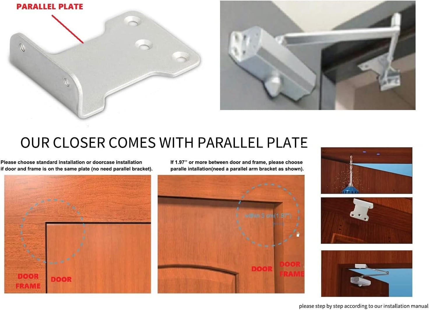
Image: This image shows the magnetic door stopper and its installation options. It illustrates both floor-mounted and wall-mounted configurations, demonstrating how it can prevent door handle damage to walls.
The included magnetic door stopper can be installed either on the floor or on the wall, depending on your preference and door configuration. It is particularly useful for keeping the door open with a simple touch, especially for doors that cannot open beyond 90 degrees or to prevent wall damage.
- Choose Location: Determine if you want a floor-mounted or wall-mounted stopper. Ensure it aligns with the door's edge when open and will prevent the door from hitting the wall.
- Mark and Drill: Mark the screw holes for both the stopper body and the magnetic plate. Drill pilot holes.
- Secure Stopper: Attach the main body of the stopper to the floor or wall. Attach the smaller magnetic plate to the bottom or side of the door.
- Test: Ensure the magnet holds the door securely when open and releases easily when pushed.
Maintenance
- Regular Cleaning: Wipe the door closer body and arm with a soft, damp cloth to remove dust and grime. Avoid abrasive cleaners.
- Check Fasteners: Periodically inspect all screws and bolts to ensure they are tight. Re-tighten if necessary to maintain proper function and safety.
- Lubrication: The hydraulic mechanism is sealed and does not require lubrication. Do not attempt to open the main body, as this may void the warranty and cause malfunction.
- Inspect for Damage: Check for any signs of wear, damage, or oil leakage. If any issues are found, discontinue use and contact customer support.
Troubleshooting
| Problem | Possible Cause | Solution |
|---|---|---|
| Door slams shut | Latching speed too fast. | Turn the Latching Regulation Valve clockwise to slow down. Make small adjustments and test. |
| Door closes too slowly | Closing speed too slow. | Turn the Speed Regulation Valve anti-clockwise to increase speed. Make small adjustments and test. |
| Door does not close completely | Latching speed too slow or arm not properly adjusted. | Turn the Latching Regulation Valve anti-clockwise. Check arm assembly for proper alignment and tightness. Ensure no obstructions. |
| Oil leakage | Damaged seal or unit. | Discontinue use immediately. This indicates a serious malfunction. Contact customer support for assistance. |
Specifications
- Brand: FLORADIS
- Model: B086XHC3FM
- Material: Alloy Steel
- Color: Silver
- Exterior Finish: Alloy Steel
- Installation Type: Screw-In
- Application: Residential and Commercial Light-Medium Doors
- Hold Open Function: Adjustable from 90° to 180°
Warranty and Support
For warranty information or technical support, please refer to the contact details provided with your purchase or visit the official FLORADIS website. Keep your purchase receipt for any warranty claims. Our customer service team is available to assist you with any questions or concerns regarding your door closer.