1. Introduction
The DEWIN RTU5024 is a GSM remote relay switch designed for access control applications. It allows you to remotely open or close gates, doors, garage doors, and other devices using a mobile phone call from authorized numbers. This system operates without call charges for authorized users, making it a cost-effective and convenient solution for various access control needs. Its global GSM network compatibility (850/900/1800/1900 MHz) ensures wide applicability.
2. Product Overview
The RTU5024 unit features a compact design with an external antenna for optimal signal reception. It includes terminals for power input and relay output, along with a SIM card slot for GSM connectivity.

Figure 1: Front view of the DEWIN RTU5024 GSM Access Control System with antenna.

Figure 2: Back view of the RTU5024 unit, showing mounting holes and SIM card compartment.

Figure 3: Bottom view of the RTU5024, highlighting the power and relay output terminal blocks.
3. Setup and Installation
3.1 SIM Card Installation
Before powering on the device, install a Mini-SIM card into the designated slot. Ensure the SIM card is active and has sufficient credit if required for SMS commands. Micro-SIM and Nano-SIM cards are not supported directly and would require an adapter (not included).
Video 1: Demonstration of SIM card installation, antenna connection, and basic wiring for the RTU5024. This video also shows the device in operation with a phone call.
3.2 Antenna Connection
Connect the provided 2G antenna to the ANT port on the device. Ensure it is securely fastened to guarantee optimal GSM signal reception.

Figure 4: The 2G antenna, which connects to the RTU5024 for GSM signal reception.
3.3 Wiring
Connect the power supply to the designated power input terminals. Connect the device to the gate opener, door lock, or other controlled equipment using the relay output terminals. Refer to the specific wiring diagram for your application. The relay output provides Normally Open (NO) and Common (COM) contacts.
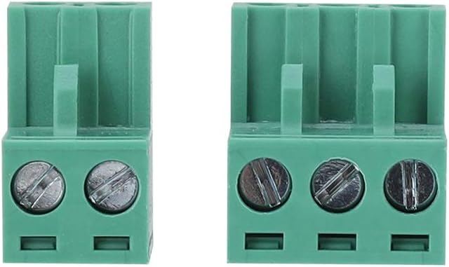
Figure 5: Close-up of the green terminal blocks for connecting power and relay output wires.
4. Operating Instructions
4.1 Power-Up and Status Indication
After connecting power, observe the red status light. When the red light flashes slowly, the device is ready to receive calls and operate.
4.2 Adding/Removing Authorized Users
Users can be added or removed using SMS commands. Refer to the detailed SMS command list in the full manual for specific instructions. Up to 200 authorized phone numbers can be configured.
4.3 Remote Control via Phone Call
To activate the relay, an authorized user simply calls the phone number of the SIM card installed in the RTU5024. The device will answer the call and perform an ON/OFF operation on the first "ring," then hang up without incurring call charges. The relay operation will send a text message confirmation to the owner or authorized call number, which can be configured by the user.

Figure 6: Illustrates a user making a phone call from a smartphone to activate the RTU5024 for remote control.
4.4 Programmable Relay Time
The relay closing or opening time is programmable, allowing customization for various applications.
5. Key Features
- Remote Relay Functionality: Control devices from anywhere with an authorized phone call, eliminating distance limitations.
- Global GSM Network Support: Compatible with 850/900/1800/1900 MHz quad-band frequencies.
- No Call Charges: The device answers and hangs up on the first ring for authorized numbers, preventing call costs.
- Enhanced Security: Uses caller ID for identification, ignoring unknown numbers. Users can be managed via SMS commands.
- High User Capacity: Supports up to 200 authorized phone numbers.
- Configurable Feedback: Relay operation can send a confirmation message to the owner or authorized caller.
- Programmable Relay Time: Customize the relay's activation duration.
- Wide Application: Suitable for controlling doors, gates, fences, garage doors, window shutters, and various machinery.

Figure 7: The RTU5024 system shown in an application controlling a garage door.

Figure 8: Examples of the RTU5024's wide application in controlling different types of access points.
6. Specifications
| Feature | Detail |
|---|---|
| Model Number | DEWINmukt6v4giw (RTU5024) |
| Product Dimensions | 1 x 1 x 1 cm |
| Item Weight | 220 g |
| Material | Metal casing |
| Drive Type | PowerSource (External Power Supply) |
| Batteries Required | No |
| Supported SIM Type | Mini-SIM |
| GSM Frequency Bands | 850/900/1800/1900 MHz |
| Max Authorized Numbers | 200 |
7. Troubleshooting
- Device not responding: Ensure the power supply is connected correctly and the device is receiving power. Check the status indicator light.
- Cannot make calls to activate: Verify that the SIM card is properly inserted and active. Ensure your phone number is added to the authorized user list. Check for GSM signal strength.
- Relay not activating: Confirm that the wiring to the controlled device (gate, door) is correct. Check the relay output connections.
- SIM card not recognized: Ensure you are using a Mini-SIM card. If using an adapter for Micro or Nano SIM, ensure it is correctly seated and the SIM card is functional.
8. Warranty and Support
For warranty information, technical support, or further assistance, please refer to the product packaging or contact DEWIN customer service directly. Keep your purchase receipt for warranty claims.