VEVOR 380V4KW
VEVOR 4KW 380V Variable Frequency Drive User Manual
Model: 380V4KW
1. Introduction
This manual provides essential information for the safe and efficient operation of your VEVOR 4KW 380V Variable Frequency Drive (VFD). Please read this manual thoroughly before installation, operation, or maintenance to ensure proper usage and to prevent damage or injury. Keep this manual for future reference.
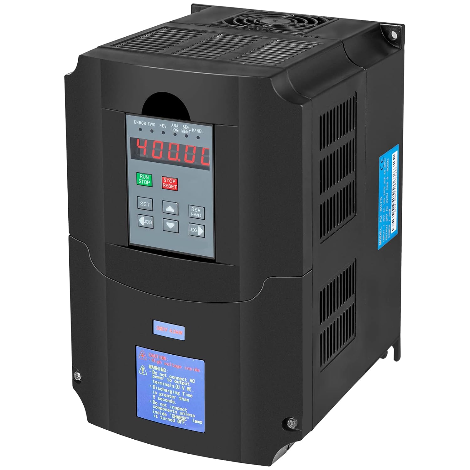
Figure 1.1: VEVOR 4KW 380V Variable Frequency Drive
2. Safety Information
Always observe the following safety precautions to prevent electric shock, fire, or personal injury.
- Electrical Hazard: Ensure the VFD is disconnected from the main power supply before any installation, wiring, or maintenance work. Wait for the charge indicator to extinguish before touching any terminals.
- Qualified Personnel: Installation and maintenance should only be performed by qualified electricians or trained personnel.
- Proper Grounding: The VFD must be properly grounded according to local electrical codes.
- Environmental Conditions: Do not expose the VFD to direct sunlight, excessive dust, corrosive gases, flammable materials, or extreme temperatures.
- Overload Protection: The VFD includes built-in overload protection. Do not bypass or modify these safety features.
3. Product Overview
The VEVOR 4KW 380V VFD is designed to control the speed of AC motors, offering flexible control modes and robust protection features.
3.1. Dimensions

Figure 3.1: Product Dimensions (Approx. 7.2" / 18.3cm H, 5.9" / 15cm W, 8.7" / 22cm D)
3.2. Separate Operation Panel
The VFD features a separate operation panel for convenient control and monitoring.

Figure 3.2: Separate Operation Panel Layout
- RUN Key: Initiates operation.
- STOP/RESET Button: Stops operation or resets errors.
- SET Key: Enters parameter setting mode.
- Reverse/Forward Keys: Changes motor direction.
- JOG Keys: Used for momentary operation or fine-tuning.
- Up/Down Arrows: Adjusts menu settings, values, or operating frequency.
3.3. Internal Components
The VFD is built with high-quality components for reliable performance.

Figure 3.3: Premium Drive Board Components
3.4. Protection Features
The VFD incorporates multiple safety protections to ensure stable and secure operation.

Figure 3.4: Multiple Protection Mechanisms
- Overload Protection: Prevents damage from excessive current draw.
- Overheat Protection: Shuts down if internal temperature exceeds safe limits.
- Over-voltage Protection: Safeguards against input voltage spikes.
- Low-voltage Protection: Protects against insufficient input voltage.
- Fuse Protection: Integrated fuses for circuit safety.
- Restart Protection: Prevents unintended restarts after power loss.
- Short Circuit Protection: Detects and protects against short circuits.
- Missing Protection: Ensures all necessary components are functioning.
4. Setup and Installation
Follow these steps for proper installation of the VFD.
4.1. Mounting
- Mount the VFD vertically on a stable, non-flammable surface.
- Ensure adequate ventilation around the unit. Maintain at least 10 cm (4 inches) clearance on all sides for proper airflow.
- Avoid mounting in areas with excessive vibration or direct heat sources.
4.2. Wiring Diagram
Refer to the following diagram for correct electrical connections. Ensure all connections are secure and comply with local electrical codes.

Figure 4.1: Typical Wiring Diagram
- Input (R, S, T): Connect the 380V 3-phase power supply to these terminals. It is recommended to install a circuit breaker upstream.
- Output (U, V, W): Connect the 3-phase motor to these terminals.
- Ground (PE): Ensure the VFD chassis is properly grounded.
- Control Terminals: Refer to the detailed wiring diagram in the full product manual for control signal connections (e.g., external start/stop, speed reference).
5. Operating Instructions
This section outlines the basic steps for operating the VFD using the control panel.
5.1. Initial Power-Up
- After completing all wiring, ensure all connections are secure.
- Apply power to the VFD. The display should illuminate.
- Check for any error codes on the display. If an error is present, refer to the Troubleshooting section.
5.2. Basic Operation
- Setting Frequency: Use the Up/Down arrow keys on the control panel to adjust the desired output frequency. This will control the motor speed.
- Starting the Motor: Press the RUN button to start the motor.
- Stopping the Motor: Press the STOP/RESET button to stop the motor.
- Changing Direction: Use the REV/FWD buttons to change the motor's rotation direction.
5.3. Parameter Settings
The VFD has numerous programmable parameters to customize its operation. Press the SET button to enter the parameter setting mode. Refer to the comprehensive parameter list in the full product manual for detailed descriptions and adjustment ranges.
- Common Parameters: Motor rated frequency, maximum output frequency, acceleration/deceleration times, V/F control mode, etc.
- Saving Settings: Ensure to save any changes made to parameters before exiting the setting mode.
6. Maintenance
Regular maintenance ensures the longevity and optimal performance of your VFD.
- Cleaning: Periodically clean the VFD's exterior and cooling fins to prevent dust buildup, which can impede heat dissipation. Use a soft, dry cloth. Do not use liquid cleaners.
- Fan Inspection: Check the cooling fan for proper operation and ensure it is free from obstructions. The VFD is designed for low-noise operation, but a malfunctioning fan can increase noise and reduce cooling efficiency.
- Terminal Connections: Annually inspect all electrical connections for tightness. Loose connections can cause overheating or intermittent operation.
- Environmental Check: Ensure the operating environment remains within specified temperature and humidity ranges.
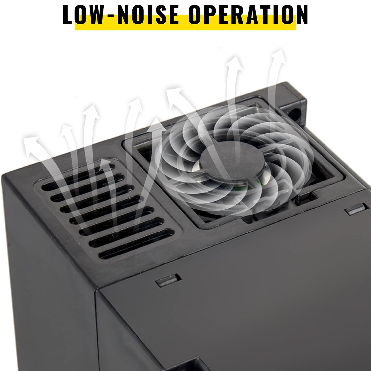
Figure 6.1: VFD Cooling Fan
7. Troubleshooting
This section provides solutions for common issues you might encounter.
| Problem | Possible Cause | Solution |
|---|---|---|
| VFD does not power on | No input power; Blown fuse; Internal fault | Check power supply; Inspect fuses; Contact support if fault persists. |
| Motor does not run | Incorrect wiring; Motor fault; VFD in fault state; Parameters not set correctly | Verify wiring; Check motor; Reset VFD; Review parameter settings. |
| Overload error (OC) | Motor overloaded; Acceleration time too short; Output short circuit | Reduce load; Increase acceleration time; Check motor and wiring for shorts. |
| Over-voltage error (OV) | Input voltage too high; Deceleration time too short | Check input voltage; Increase deceleration time. |
| Overheat error (OH) | Insufficient ventilation; Ambient temperature too high; Fan malfunction | Improve ventilation; Reduce ambient temperature; Check cooling fan. |
For persistent issues or error codes not listed, please consult the full product manual or contact VEVOR customer support.
8. Specifications
Key technical specifications for the VEVOR 4KW 380V Variable Frequency Drive.
| Feature | Specification |
|---|---|
| Model Number | 380V4KW |
| Input Voltage | 380V (3-phase) |
| Output Voltage | 380V (3-phase) |
| Power Rating | 4KW |
| Product Dimensions (L x W x H) | 27.94 x 25.4 x 22.86 cm (Approx. 11 x 10 x 9 inches) |
| Product Weight | 2.9 kg (Approx. 6.4 lbs) |
| Control Mode | V/F control, Vector control |
| Frequency Adjustment | Digital setting, Analog setting, Serial communication, PID setting |
9. Warranty and Support
For warranty information, technical support, or spare parts inquiries, please contact VEVOR customer service through their official website or the retailer from whom you purchased the product. Please have your model number (380V4KW) and purchase details ready when contacting support.
For more information on product applications, refer to the examples below:

Figure 9.1: Typical VFD Applications
Ask a question about this manual
Ask about setup, troubleshooting, compatibility, parts, safety, or missing instructions. Manuals+ will review the question and use this page’s manual context to help answer it.