1. Introduction
This manual provides essential information for the installation, operation, and maintenance of the DollaTek FX3U-24MR DC24V Programmable Logic Controller (PLC). The FX3U-24MR is an industrial-grade control board designed for various automation tasks, featuring a 32-bit microcontroller for robust performance and high-speed processing.
Key features include:
- Industrial-grade 32-bit microcontroller for strong anti-interference and fast operation.
- Supports Ladder Logic programming language.
- Compatible with GX-Developer and GX-work2 programming software.
- Supports Human Machine Interface (HMI) connection.
- Integrated programming port for program uploading, downloading, and monitoring.

Figure 1.1: DollaTek FX3U-24MR PLC with protective casing.

Figure 1.2: DollaTek FX3U-24MR PLC circuit board components.
2. Setup and Wiring
Proper setup and wiring are crucial for the safe and correct operation of the FX3U-24MR PLC. Ensure the power supply is disconnected before making any connections.
2.1 Power Supply Connection
The PLC requires a DC24V power supply. Connect the positive (+) terminal of the 24V power supply to the '24V' terminal on the PLC and the negative (-) terminal to the '0V' terminal.
2.2 Input and Output Wiring
The FX3U-24MR features 14 digital input points (X0-X15) and 10 relay output points (Y0-Y11). Inputs X0-X5 can function as high-speed counting inputs up to 12KHz. The relay outputs can control AC contactors, intermediate relays, and solenoid valves, with a maximum current of 5A per output.

Figure 2.1: Detailed pinout and wiring diagram for the FX3U-24MR PLC.
Digital Inputs (X0-X15): These are low-level NPN inputs. Connect external sensors or switches to these terminals. Note that X point input is negative.
Relay Outputs (Y0-Y11): These are relay contacts. Connect the load to be controlled between the common terminal and the respective Y output terminal. Ensure the load's voltage and current ratings do not exceed the PLC's specifications (Max. 5A).
2.3 Analog Input/Output Wiring
The PLC includes 6 analog input channels (AD0-AD5) and 2 analog output channels (DA0-DA1).
- Analog Inputs: AD0-AD2 support 0-10V voltage input. AD3-AD5 support 0-20mA current input.
- Analog Outputs: DA0-DA1 provide 0-10V voltage output.
Refer to the wiring diagrams for correct connection of analog sensors and actuators.

Figure 2.2: Example wiring diagram with loads and RS485 communication.
2.4 Communication Ports
The PLC is equipped with RS232 and RS485 communication interfaces. These ports are used for programming, HMI communication, and data exchange.
- RS232: Typically used for programming and debugging with a PC.
- RS485: Suitable for multi-device communication in industrial networks.
3. Operating Instructions
The FX3U-24MR PLC supports programming, uploading, debugging, and monitoring using Ladder Logic programming software such as GX-Developer or GX-work2.
3.1 Programming Mode
The PLC operates in a programming mode that allows for the creation, modification, and transfer of control programs. The programming port serves as the interface for these operations.
- Programming: Develop your control logic using Ladder Logic in GX-Developer or GX-work2.
- Uploading/Downloading: Transfer programs between the PC and the PLC.
- Debugging/Monitoring: Observe the PLC's real-time status and program execution for troubleshooting and verification.
3.2 Analog Input Reading
To read analog input values, use the RD3A instruction. This instruction reads the instantaneous value from the specified analog module and saves it to a data register.

Figure 3.1: Analog reading instruction (RD3A).
- M1: Module number (set to 0 for host).
- M2: Analog input channel number (e.g., K0-K5, corresponding to AD0-AD5).
- D: Data register to save the read value (e.g., D0).
3.3 Analog Output Control
To control analog output values, use the WR3A instruction. This instruction writes a specified data value to the analog output module.

Figure 3.2: Analog output instruction (WR3A).
- M1: Module number (set to 0 for host).
- M2: Analog input channel number (e.g., K0-K1).
- D: Data to write to the analog module (range 0-4095).
3.4 High-Speed Pulse Output and Pulse Width Modulation (PWM)
The FX3U-24MR supports high-speed pulse output and PWM functions, essential for controlling stepper motors, servo motors, and other precise motion control applications.
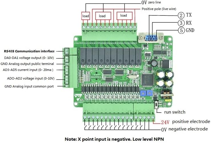
Figure 3.3: High-speed pulse output and PWM parameters.
The PLC supports 8-way pulse output (Y0-Y3 frequency 100K, Y4-Y7 frequency 10K) and 6-way pulse width modulation (PWM) output (Y0-Y3 frequency 100K).
3.5 Interrupt Description
The PLC supports various interrupt types for responsive control, including external interrupts, timer interrupts, and counter interrupts.

Figure 3.4: Interrupt description table.
- External Interrupts: Supported on inputs X0-X5 with specific interrupt numbers and inhibit bits.
- Timer Interrupts: Timer interrupt pointer is I600, with inhibit M8056. Interrupt time range I601 (1MS) - I699 (99MS).
- Counter Interrupts: Specific pointer numbers correspond to interrupt inhibit bits.
4. Specifications
| Feature | Specification |
|---|---|
| Product Type | FX3U-24MR |
| Power Supply | DC24V |
| Digital Inputs | 14 points (X0-X15), X0-X5 support 12KHz high-speed counting |
| Digital Outputs | 10 relay points (Y0-Y11), Max. 5A per output |
| Analog Inputs | AD0-AD2 (0-10V), AD3-AD5 (0-20mA) |
| Analog Outputs | 2 points (0-10V) |
| Memory Capacity | 8000 steps |
| Upload Baud Rate | 38.4 Kbps |
| Programming Software | GX-Developer, GX-work2 |
| Dimensions (Board) | Approximately 125mm x 100mm |
| Maximum Operating Temperature | 60°C |
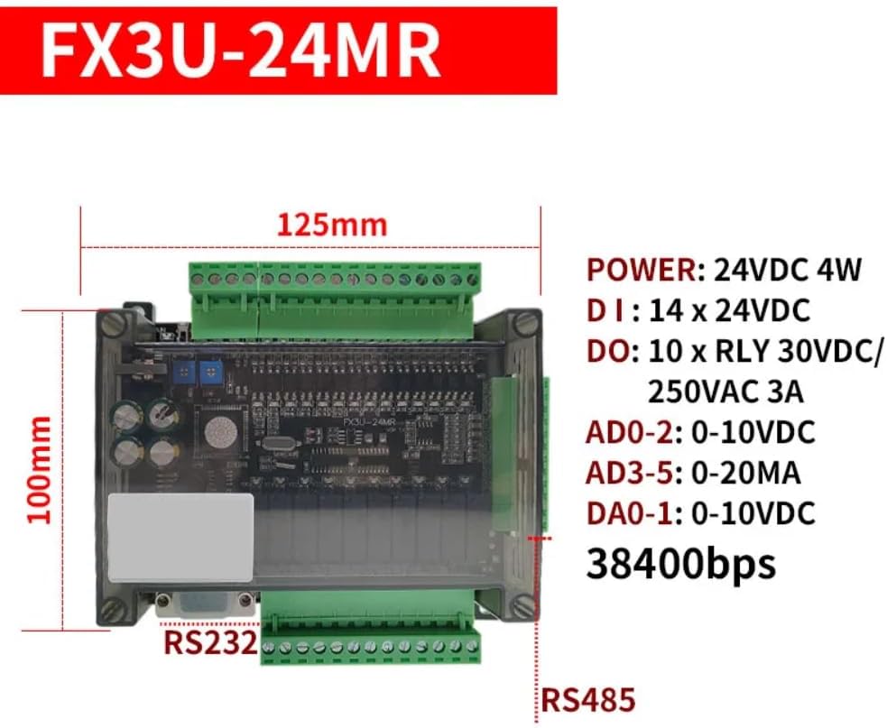
Figure 4.1: FX3U-24MR PLC dimensions.
5. Maintenance
To ensure the longevity and reliable operation of your DollaTek FX3U-24MR PLC, follow these general maintenance guidelines:
- Keep Clean: Regularly clean the PLC and its surroundings to prevent dust and debris accumulation, which can affect performance and lead to overheating. Use a soft, dry cloth.
- Environmental Control: Operate the PLC within its specified temperature and humidity ranges. Avoid exposure to direct sunlight, excessive moisture, or corrosive environments.
- Connection Integrity: Periodically check all wiring connections for tightness and signs of corrosion. Loose connections can cause intermittent operation or damage.
- Power Supply Stability: Ensure a stable and clean DC24V power supply. Voltage fluctuations can impact PLC performance.
6. Troubleshooting
This section provides general guidance for common issues. For complex problems, consult the programming software documentation or contact technical support.
- PLC Not Powering On: Verify the DC24V power supply connections and ensure the power source is active and providing the correct voltage.
- Program Upload/Download Failure: Check the RS232/RS485 communication cable connection. Ensure the correct COM port is selected in the programming software and the baud rate matches the PLC's setting (38.4 Kbps). Verify that the correct drivers for your communication cable are installed.
- Input Not Responding: Check the wiring of the input device (sensor/switch) to the PLC's input terminal. Ensure the input device is functioning correctly and providing the expected signal (low-level NPN).
- Output Not Activating: Verify the wiring of the load to the PLC's output terminal. Check the load itself for functionality. In the programming software, monitor the output status to confirm the PLC is commanding the output to activate. Ensure the load's current draw does not exceed 5A.
- Timing Function Issues: If timing functions are not operating as expected, review your Ladder Logic program for correct timer instruction usage and parameter settings. Ensure the PLC's internal clock (if used) is correctly configured.
7. Warranty and Support
For information regarding product warranty, technical support, or service, please refer to the documentation provided at the time of purchase or contact your vendor directly. DollaTek provides support for its products, and specific contact details can usually be found on their official website or through authorized distributors.


