
1. Introduction
This manual provides essential information for the safe and efficient installation, operation, and maintenance of the Festo VABF-S4-2-R1C2-C-10 ZA Pneumatic Valve Assembly Gauge Stop. Please read this manual thoroughly before using the product and keep it for future reference.
2. Safety Instructions
Always observe general safety regulations and accident prevention guidelines when working with pneumatic systems. Improper use or installation can lead to serious injury or damage to equipment.
- Ensure that only qualified personnel install and maintain this device.
- Depressurize the system completely before performing any installation, maintenance, or repair work.
- Verify that all connections are secure and leak-free before operating the system.
- Do not exceed the maximum operating pressure specified in the technical data.
- Protect the device from contamination, moisture, and extreme temperatures.
3. Product Description
The Festo VABF-S4-2-R1C2-C-10 ZA is a pneumatic valve assembly integrated with a gauge stop function. It is designed for controlling pneumatic circuits and monitoring pressure within the system. The assembly typically includes a valve mechanism and a pressure gauge for visual indication.
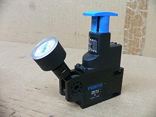
Figure 1: Overview of the Festo VABF-S4-2-R1C2-C-10 ZA Pneumatic Valve Assembly Gauge Stop. The image shows the main body of the valve assembly, a blue lever on top, and an attached pressure gauge on the side.
4. Setup and Installation
Before installation, ensure that the product matches the required specifications for your application. Identify the model number on the device label.
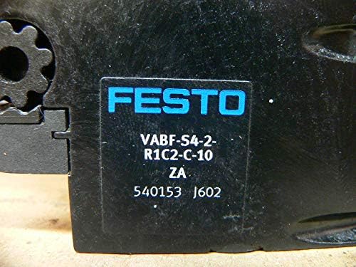
Figure 2: Close-up view of the product label showing the Festo brand and model number VABF-S4-2-R1C2-C-10 ZA.
- Mounting: Securely mount the valve assembly to a stable surface or panel using appropriate fasteners. Ensure there is sufficient space for connections and operation.
- Pneumatic Connections: Connect the pneumatic lines to the designated ports. Refer to the markings on the valve for inlet and outlet ports. Use appropriate fittings and ensure all connections are tight to prevent leaks.
- Gauge Installation: If the pressure gauge is not pre-installed, carefully screw it into the designated port on the valve assembly. Do not overtighten.
- System Integration: Integrate the valve assembly into your pneumatic circuit according to your system design.
5. Operating Instructions
The VABF-S4-2-R1C2-C-10 ZA valve assembly is designed for straightforward operation.
- Valve Actuation: The valve is typically actuated by a lever or button (e.g., the blue lever shown in Figure 1). Move the lever to the desired position to control the air flow.
- Pressure Monitoring: The integrated pressure gauge displays the current pressure in the connected line. Monitor this gauge to ensure the system operates within safe and specified pressure ranges.
- Gauge Stop Function: The gauge stop feature allows for isolation of the pressure gauge from the main pneumatic line for maintenance or replacement without depressurizing the entire system. Consult your system's specific design for how this function is engaged.
6. Maintenance
Regular maintenance ensures the longevity and reliable operation of the valve assembly.
- Routine Inspection: Periodically inspect the valve assembly for any signs of wear, damage, or leaks. Check all connections for tightness.
- Cleaning: Keep the exterior of the valve assembly clean. Use a soft, damp cloth. Do not use aggressive cleaning agents or solvents.
- Filter Maintenance: Ensure that upstream air filters are regularly cleaned or replaced to prevent contaminants from entering the valve.
- Seal Replacement: If leaks are detected from the valve body, seals may need replacement. This should only be performed by qualified personnel using original Festo spare parts.
7. Troubleshooting
This section addresses common issues you might encounter.
| Problem | Possible Cause | Solution |
|---|---|---|
| Air Leakage | Loose connections, damaged seals, cracked housing. | Tighten connections. Inspect and replace damaged seals. Replace the valve if housing is cracked. |
| Valve Not Actuating | No air supply, insufficient pressure, internal blockage, mechanical failure. | Check air supply and pressure. Inspect for blockages. Contact Festo support if mechanical failure is suspected. |
| Gauge Reading Incorrect | Faulty gauge, gauge stop engaged, incorrect calibration. | Check if gauge stop is disengaged. Replace faulty gauge. Consult a specialist for calibration if necessary. |
8. Specifications
Technical data for the Festo VABF-S4-2-R1C2-C-10 ZA Pneumatic Valve Assembly Gauge Stop:
| Parameter | Value |
|---|---|
| Manufacturer | FESTO |
| Part Number | VABF-S4-2-R1C2-C-10 ZA |
| Item Weight | 1.32 pounds |
| Product Dimensions (L x W x H) | 7.09 x 6.3 x 8.27 inches |
| Item Package Quantity | 1 |
| Brand | Festo |
9. Warranty and Support
For information regarding product warranty, please refer to the official Festo warranty policy available on their website or contact your local Festo representative. For technical support, spare parts, or service, please contact Festo customer service with your product model number and any relevant details.
Festo Official Website: www.festo.com


