
ANMBEST ANMBEST_MD241, ANMBEST_MD242
ANMBEST DB37 Solderless RS232 D-SUB Serial Female Adapter Connector Breakout Board User Manual
Model: ANMBEST_MD241, ANMBEST_MD242
1. Introduction
This manual provides detailed instructions for the ANMBEST DB37 Solderless RS232 D-SUB Serial Female Adapter Connector Breakout Board. This device is designed to facilitate easy and reliable termination of DB37 serial connections without the need for soldering. It is suitable for various industrial and computing applications requiring custom pinouts or cable lengths.
2. Product Overview
The ANMBEST DB37 Solderless Connector is engineered for durability and ease of use. It features a female DB37 port and screw-type terminal blocks for secure wire connections. The design emphasizes a compact form factor and clear terminal markings to simplify installation and reduce wiring errors.
Key Features:
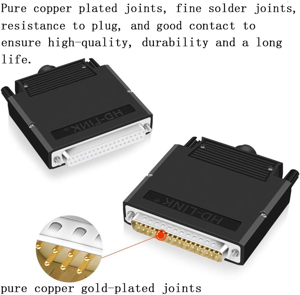
- High-Quality Construction: Features pure copper plated joints and an environmentally friendly PP engineering material housing for enhanced durability and reliable contact.
- Solderless Design: Utilizes 128-type environmental protection copper terminals, eliminating the need for soldering tools and simplifying wiring.
- Error Reduction: Clearly marked terminal block areas ensure proper wire termination, minimizing installation errors.
- Compact Form Factor: With a thickness of only 16mm, this adapter is thinner than standard solderless connectors, allowing for use in confined spaces.
- Wide Compatibility: Suitable for connecting various serial devices, including tax control machines, digital cameras, PLCs, PDAs, MODEMs, set-top boxes, barcode machines, and industrial instrumentation.

3. Package Contents
Verify that all items listed below are included in your package:
- 1 x DB37 Female Solderless Connector
- 1 x Cable Pressing Plate
- 2 x Screws (for case assembly)
- 2 x Long Bolts (for mounting)
- 1 x 5mm Tail Pipe
- 1 x 6mm Tail Pipe
- 1 x 7.5mm Tail Pipe
- 1 x 8.5mm Tail Pipe

4. Technical Specifications
| Feature | Specification |
|---|---|
| Product Name | Thin DB37 Solderless Module |
| Plug Type | Female |
| Connector Material | Pure copper plated joint |
| Contact Material | Copper |
| Housing Material | Environmentally friendly PP engineering materials |
| Shell Type | Folding snap-on |
| Opening Size (Cable Port) | 10.5mm / 0.41 inches |
| Thickness | 16mm / 0.63 inches |
| Cable Specification | 26-16 AWG |
| Torque | 0.2Nm (1.7Lb-In.) |
| Dimensions (L x W x H) | 76mm × 73.5mm × 16mm / 2.99″ × 2.89″ × 0.63″ |
| Item Weight | 2.89 ounces |
5. Setup Instructions
Follow these steps to assemble and connect your DB37 solderless adapter:
- Open the Case: Gently unclip and open the folding snap-on case to expose the terminal block.
- Prepare Wires: Strip approximately 5-7mm of insulation from the ends of your wires (26-16 AWG).
- Connect Wires to Terminals:
- Identify the desired pin numbers on the terminal block. The terminals are clearly marked from 1 to 37.
- Use a small screwdriver to loosen the screw for the corresponding terminal.
- Insert the stripped end of the wire into the terminal opening.
- Tighten the screw to secure the wire. Ensure the wire is firmly held and no stray strands are exposed. The recommended torque is 0.2Nm (1.7Lb-In.).

Image 5.1: Illustrates the solderless wiring process, showing a wire being inserted into one of the clearly marked screw terminals on the breakout board. 
Image 5.2: Detailed view of the terminal block area, highlighting the clear numbering for each pin (1-37) to aid in correct wire termination. - Install Cable Pressing Plate (Optional but Recommended):
The cable pressing plate helps prevent accidental removal of connected wires. Once all wires are connected, position the plate over the wires and secure it if desired.

Image 5.3: The cable pressing plate installed, demonstrating how it secures the wires and provides strain relief, preventing accidental disconnections. - Select and Install Tail Pipe: Choose the appropriate tail pipe (5mm, 6mm, 7.5mm, or 8.5mm) that best fits the diameter of your cable. This provides strain relief and protects the cable entry point. Insert the cable through the chosen tail pipe before closing the case.
- Close the Case: Carefully close the folding snap-on case, ensuring all wires are properly routed and not pinched. The case will click securely into place.
- Secure with Screws: Use the provided screws to further secure the case halves together, if desired, for a more robust assembly.
- Mounting (Optional): Use the long bolts to mount the adapter if your application requires it.

6. Operating Instructions
Once assembled, the ANMBEST DB37 Solderless Adapter functions as a passive connection point. Ensure that the connected devices are powered off before making or breaking connections to prevent potential damage.
- Connection: Plug the female DB37 connector into the corresponding male DB37 port on your serial device or cable.
- Secure Connection: If your device has thumbscrews or clips for the DB37 port, use them to secure the adapter firmly in place.
- Functionality Check: After connecting, power on your devices and verify communication or data transfer as required by your application.
7. Maintenance
The ANMBEST DB37 Solderless Adapter requires minimal maintenance to ensure long-term performance.
- Cleaning: Keep the connector and terminals free from dust and debris. Use a dry, soft cloth for cleaning. Avoid liquid cleaners.
- Connection Integrity: Periodically check the screw terminals to ensure wires remain securely fastened. Retighten if necessary, but do not overtighten.
- Environmental Conditions: Store and operate the adapter in a dry environment, away from extreme temperatures and corrosive substances.
8. Troubleshooting
If you encounter issues with your DB37 solderless adapter, consider the following:
- No Communication/Intermittent Connection:
- Verify that all wires are correctly connected to their designated terminals according to your pinout diagram.
- Ensure all terminal screws are tightened securely. Loose connections are a common cause of intermittent issues.
- Check the integrity of your cable. Test with a known good cable if possible.
- Confirm that the DB37 connector is fully seated and secured to the device port.
- Physical Damage:
- Inspect the connector pins for any bends or damage.
- Check the case for cracks or damage that might expose internal components.
- Incorrect Pinout: Double-check your wiring against the required pinout for your specific application. A common issue is misinterpreting pin assignments.
9. Warranty and Support
For warranty information or technical support, please refer to the ANMBEST official website or contact their customer service directly. Keep your purchase receipt for warranty claims.
ANMBEST Official Website: Visit ANMBEST on Amazon
Ask a question about this manual
Ask about setup, troubleshooting, compatibility, parts, safety, or missing instructions. Manuals+ will review the question and use this page’s manual context to help answer it.