RECOIL RCK4
RECOIL True 4 Gauge Complete CCA Amplifier Wiring Kits with OFC RCA Cable - Instruction Manual
Model: RCK4
Introduction
This instruction manual provides detailed information for the installation and proper use of your RECOIL True 4 Gauge Complete CCA Amplifier Wiring Kit. This kit is designed to provide optimal power transfer and signal clarity for your car audio amplifier system. Please read all instructions carefully before beginning installation.

Image: RECOIL Amplifier Wiring Kits are comprehensive, providing all necessary components for car audio system wiring.
Package Contents
Your RECOIL True 4 Gauge Complete CCA Amplifier Wiring Kit includes the following components:
- 17ft (5.5 meters) Oxygen Free Copper (OFC) 2-Channel Helical twisted construction RCA interconnect cable.
- 17ft (5.5 meters) Premium Frosted Blue 4 Gauge power wire with pre-attached ring terminal.
- 3ft (0.95 meters) Premium Frosted Black 4 Gauge ground wire with pre-attached ring terminal.
- 17ft (5.5 meters) Blue 18 Gauge remote turn-on lead wire.
- 25ft (8.0 meters) Premium Frosted Blue/Black 16 Gauge speaker wire.
- One RECOIL ANL/Mini-ANL Fuse-holder with a 120A ANL fuse.
- One Black rubber firewall grommet.
- Four 4 Gauge Nickel Plated Ring terminals with blue/black boots.
- Five 18 Gauge Spade terminals with blue/black boots.
- One Red 18 Gauge butt connector.
- Ten 6-inch Black zip ties.

Image: A complete view of all components included in the RECOIL amplifier wiring kit.
Specifications
| Feature | Detail |
|---|---|
| Brand | RECOIL |
| Model Number | RCK4 |
| Power Wire Gauge | 4 Gauge (CCA) |
| Power Wire Length | 17 ft (5.5 m) |
| Ground Wire Gauge | 4 Gauge |
| Ground Wire Length | 3 ft (0.95 m) |
| RCA Cable Type | 2-Channel OFC Helical Twisted |
| RCA Cable Length | 17 ft (5.5 m) |
| Remote Wire Gauge | 18 Gauge |
| Remote Wire Length | 17 ft (5.5 m) |
| Speaker Wire Gauge | 16 Gauge |
| Speaker Wire Length | 25 ft (8.0 m) |
| Fuse Holder Type | ANL/Mini-ANL |
| Fuse Rating | 120A ANL |
| Special Feature | Heat Resistant |
| Maximum Voltage | 24 Volts (DC) |

Image: Close-up view of the 4AWG wire, detailing its construction and specifications.
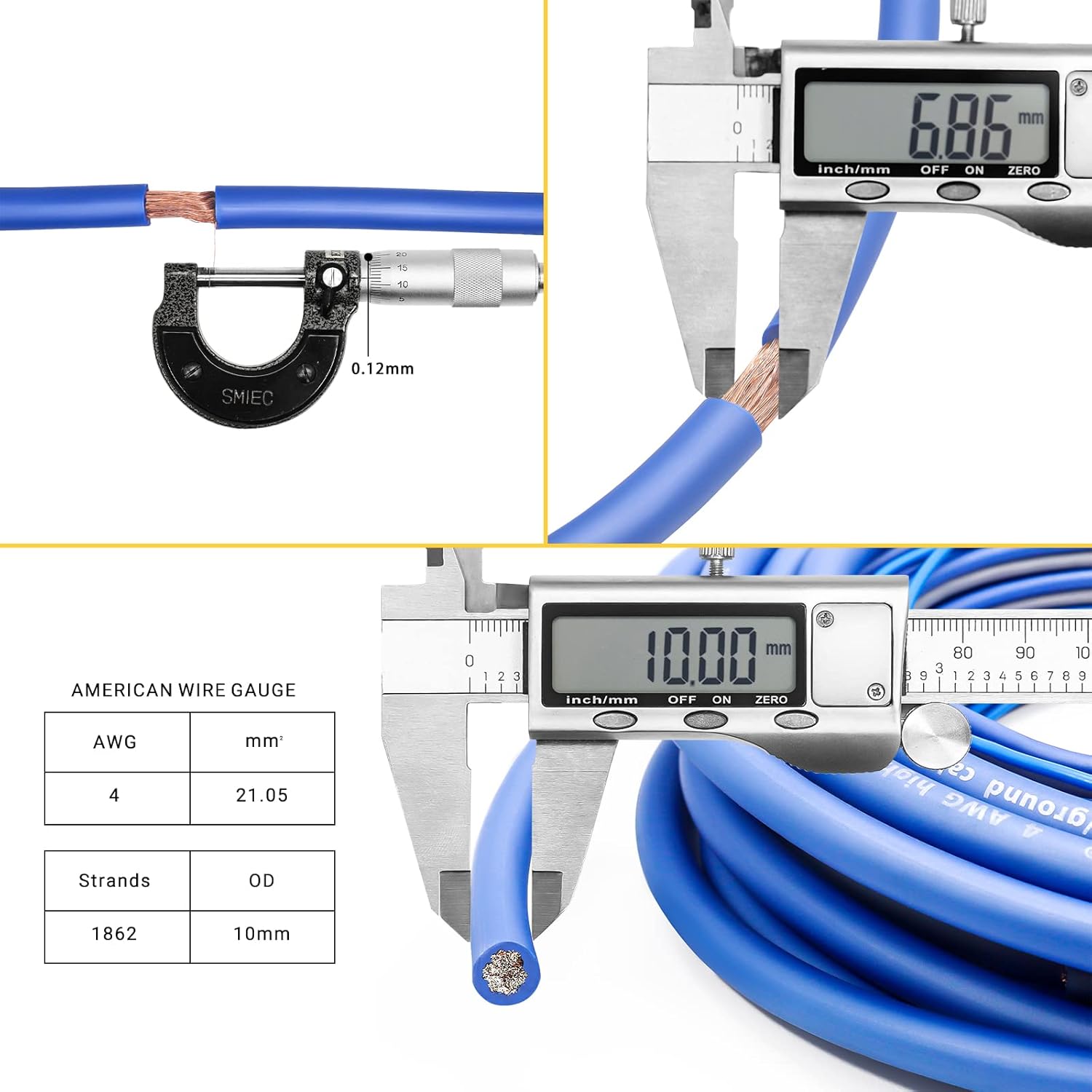
Image: Visual confirmation of wire gauge and strand measurements for the 4AWG cable.
Setup and Installation
Safety Precautions
- Always disconnect the vehicle's negative battery terminal before starting any electrical work.
- Wear appropriate safety gear, including eye protection.
- Ensure all connections are secure and properly insulated to prevent short circuits.
- Route wires away from moving parts, sharp edges, and heat sources.
- Consult a professional if you are unsure about any part of the installation process.
Installation Steps
- Power Wire Installation:
Route the 17ft (5.5m) blue 4 Gauge power wire from the vehicle's battery to the amplifier location. Use the included firewall grommet when passing the wire through the firewall to protect it from sharp edges. Connect the pre-attached ring terminal to the positive (+) terminal of the battery. Do not connect the other end to the amplifier yet.

Image: High quality CCA wire ensures maximum and reliable power transfer.

Image: Detailed view of the Recoil power wire, highlighting its quality construction.
- Fuse Holder Installation:
Install the ANL/Mini-ANL fuse holder within 18 inches (45 cm) of the battery on the power wire. Cut the power wire and strip the ends. Securely connect the power wire to both sides of the fuse holder. Insert the 120A ANL fuse into the holder. This provides critical protection for your system.

Image: The fuse holder provides essential protection for your amplifier system.
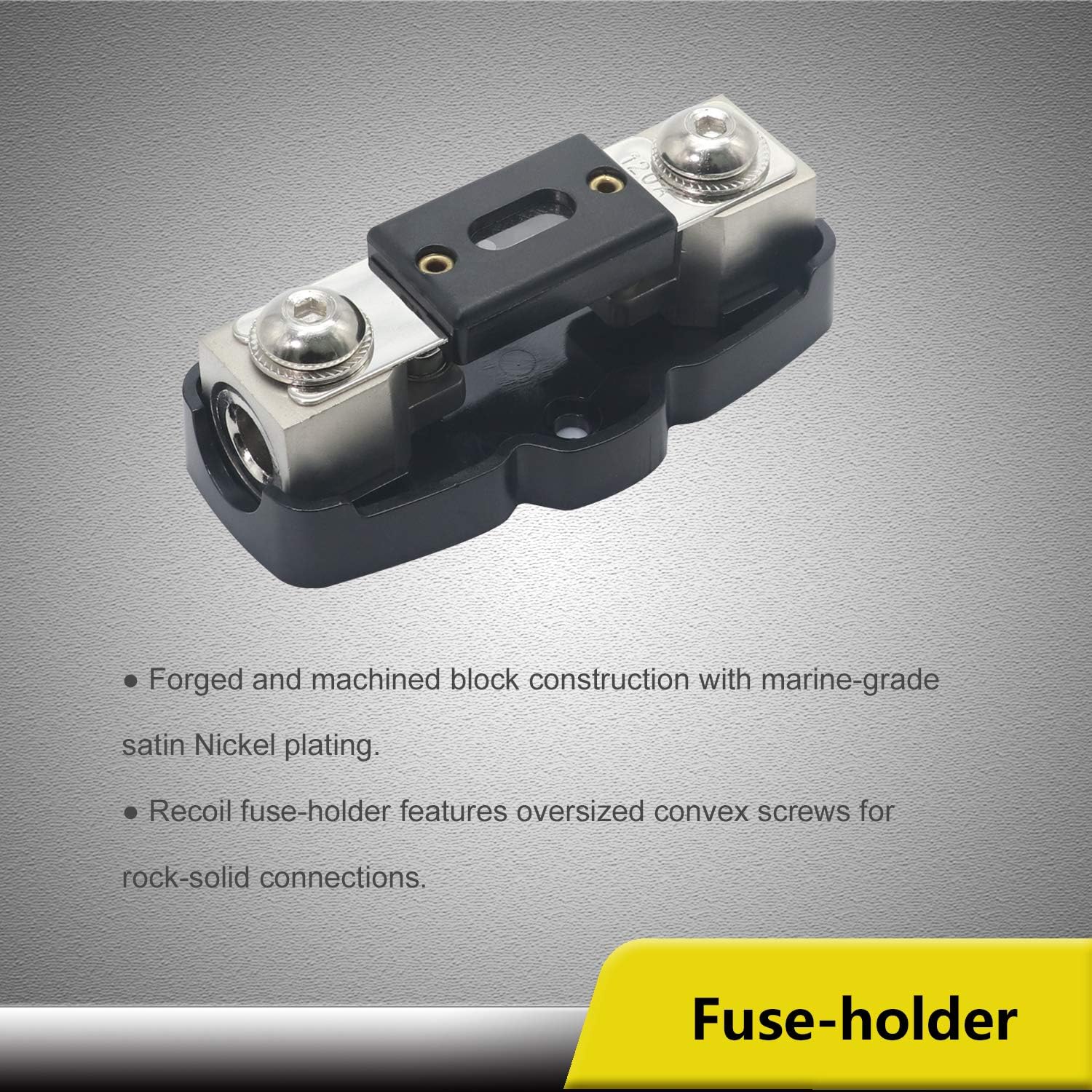
Image: Detailed view of the Recoil fuse holder, emphasizing its robust construction.
- Ground Wire Installation:
Route the 3ft (0.95m) black 4 Gauge ground wire from the amplifier location to a clean, unpainted metal surface on the vehicle's chassis. Ensure the contact point is free of paint, rust, or dirt for optimal conductivity. Connect the pre-attached ring terminal to this ground point. Connect the other end to the ground terminal of your amplifier.

Image: Detailed view of the Recoil ground wire, highlighting its quality construction.
- RCA Cable Installation:
Route the 17ft (5.5m) 2-channel OFC RCA interconnect cable from your head unit (source unit) to the amplifier. It is recommended to route RCA cables on the opposite side of the vehicle from power wires to minimize noise interference. Connect the RCA plugs to the corresponding input jacks on your amplifier and output jacks on your head unit.

Image: OFC RCA cables deliver superior signal clarity for an optimal listening experience.

Image: Detailed view of the Recoil RCA cables, emphasizing their OFC construction.
- Remote Turn-On Wire Installation:
Route the 17ft (5.5m) blue 18 Gauge remote turn-on lead wire from your head unit's remote output to the remote input terminal on your amplifier. This wire tells the amplifier when to turn on and off with your head unit.
- Speaker Wire Installation:
Route the 25ft (8.0m) blue/black 16 Gauge speaker wire from the amplifier's speaker output terminals to your speakers. Ensure correct polarity (+ to + and - to -) for each speaker. Use the included spade terminals and butt connector as needed for secure connections.

Image: Detailed view of the Recoil speaker wire, designed for optimal audio performance.
- Final Connections:
Once all wires are routed and prepared, connect the power wire to the amplifier's positive (+) terminal. Double-check all connections for tightness and proper insulation. Reconnect the vehicle's negative battery terminal.
Operating
Once the RECOIL amplifier wiring kit is correctly installed, the amplifier will power on automatically when your vehicle's head unit is turned on, thanks to the remote turn-on wire. The kit itself does not require specific "operation" beyond proper installation. Ensure your amplifier settings (gain, crossover, etc.) are adjusted according to your audio system's requirements and amplifier manual.
Maintenance
The RECOIL amplifier wiring kit is designed for durability and requires minimal maintenance. Periodically inspect all connections for corrosion or looseness. Ensure wires are not pinched or exposed to excessive heat. If the fuse blows, replace it only with a fuse of the same type and rating (120A ANL) to prevent damage to your system.
Troubleshooting
| Problem | Possible Cause | Solution |
|---|---|---|
| Amplifier does not turn on. | Blown fuse in fuse holder. Loose power or ground connection. Remote turn-on wire not connected or faulty. | Check and replace fuse if necessary. Verify all power and ground connections are secure. Ensure remote wire is connected to head unit's remote output and amplifier's remote input. |
| No sound from speakers. | RCA cables not connected or faulty. Speaker wires not connected or incorrect polarity. Amplifier settings incorrect. | Check RCA connections at head unit and amplifier. Verify speaker wire connections and polarity. Refer to amplifier manual for correct settings. |
| Engine noise or whine through speakers. | Poor ground connection. RCA cables routed too close to power wires. Faulty RCA cables. | Ensure ground point is clean and secure. Reroute RCA cables away from power wires. Test with different RCA cables if possible. |
Warranty and Support
For warranty information and technical support, please refer to the RECOIL official website or contact RECOIL customer service directly. Keep your proof of purchase for warranty claims.
RECOIL Audio was founded in 2004 with the goal of providing great, affordable products. They are vertically integrated with Engineering, Sales, and Marketing teams located in Phoenix, Arizona, USA.
You can visit the RECOIL Store on Amazon for more products and information: RECOIL Amazon Store
Ask a question about this manual
Ask about setup, troubleshooting, compatibility, parts, safety, or missing instructions. Manuals+ will review the question and use this page’s manual context to help answer it.