1. Product Overview
The Youmile MAX7219 8x32 LED Dot Matrix Display Module is an integrated serial input/output common-cathode display driver designed to interface microprocessors with 8-digit 7-segment LED displays, bar graph displays, or up to 64 individual LEDs. This module is ideal for various electronic projects, including those involving Arduino and Raspberry Pi.
It features an on-chip B-type BCD encoder, multi-channel scan loop, segment word driver, and 8x8 static RAM for data storage. A single external resistor is used to set the segment current for each LED, simplifying design.
The convenient 4-wire serial interface is compatible with all common microprocessors, allowing individual data addressing without requiring full display rewrites during updates. The MAX7219 also provides user control over data encoding.
The device includes a 150μA low-power shutdown mode, analog and digital brightness control, and a scan limit register that allows users to display 1 to 8 bits of data. A detection mode is also available to light up all LEDs for testing.
Only three I/O ports are required to drive a single dot matrix, ensuring a flicker-free display. The module supports cascading multiple units through its input and output interfaces, enabling the creation of larger display arrays. Each module can drive an 8x8 common cathode array and features 64 fixed screw holes with a 3mm aperture for secure mounting.
2. Features
- Drives one 8x8 common cathode dot matrix LED display.
- Operating Voltage: 5V.
- Dimensions: 12.8 x 3.2 x 1.3 cm.
- Features 64 fixed screw holes with a 3mm diameter for secure mounting.
- Equipped with input and output interfaces, supporting cascading of multiple modules for larger displays.
- Requires only 3 I/O ports to drive a single dot matrix, ensuring efficient use of microcontroller pins.
- Integrated serial input/output common-cathode display driver.
- On-chip B-type BCD encoder, multi-channel scan loop, segment word driver, and 8x8 static RAM.
- Analog and digital brightness control.
- Low-power shutdown mode (150μA).
3. Setup and Wiring
3.1 Module Components

Figure 3.1: Top view of the MAX7219 dot matrix module, highlighting the MAX7219 chip and input/output pin headers.

Figure 3.2: Bottom view of the MAX7219 dot matrix module, illustrating the circuit board layout and mounting points.
3.2 Wiring Instructions
The module features an input port on the left side and an output port on the right side. This design facilitates both single-module operation and cascading multiple modules.
- Single Module Control: To control a single MAX7219 module, connect its input port directly to your microcontroller (CPU).
- Cascading Multiple Modules: For larger displays, multiple modules can be cascaded. Connect the input of the first module to the CPU. Then, connect the output of the first module to the input of the second module. Continue this pattern, connecting the output of each module to the input of the next in the chain.
Example Wiring for 51 MCU:
- VCC → 5V
- GND → GND
- DIN → P2.2
- CS → P2.1
- CLK → P2.0

Figure 3.3: An example setup showing the MAX7219 module driving four cascaded 8x8 dot matrix displays, connected via jumper wires.
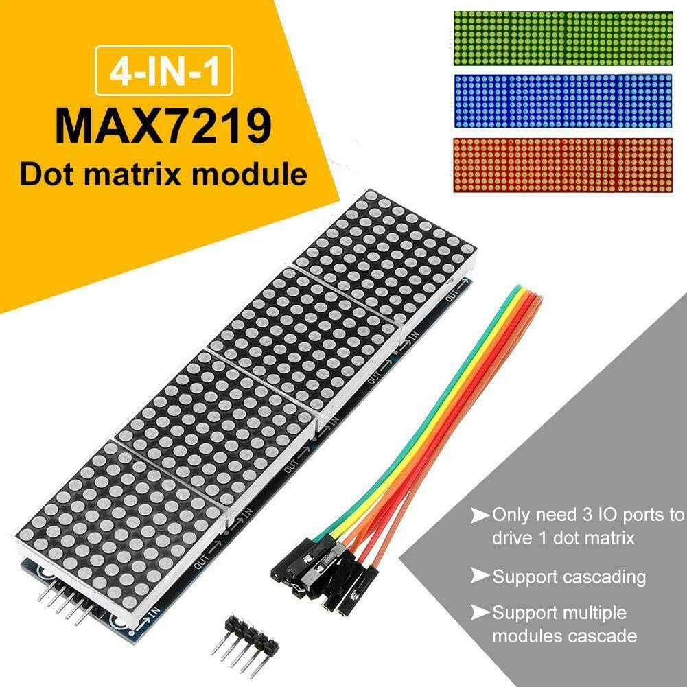
Figure 3.4: A diagram detailing the 4-in-1 MAX7219 dot matrix module, emphasizing its input/output pins and the method for cascading multiple units.
4. Operating Instructions
Once wired correctly, the MAX7219 module can be programmed using a microcontroller (e.g., Arduino, Raspberry Pi) to display various patterns, text, and animations on the connected LED dot matrix. Libraries are commonly available for popular microcontrollers to simplify programming the MAX7219 chip.
4.1 Basic Display Functions
- Individual LED Control: Each LED in the 8x8 matrix can be turned on or off independently.
- Brightness Control: The overall brightness of the display can be adjusted through software commands.
- Text Display: Characters and strings can be scrolled or displayed statically across the matrix.
- Graphics and Animations: Custom patterns, images, and animations can be created and displayed.
- Cascaded Displays: When multiple modules are cascaded, they act as a single, larger display, allowing for more extensive visual outputs.
4.2 Programming Considerations
Refer to the specific MAX7219 library documentation for your chosen microcontroller platform for detailed programming examples and API references. Key functions typically include initializing the display, setting brightness, clearing the display, and writing data to specific LED positions or the entire matrix buffer.
5. Media Gallery
5.1 Product Images

Figure 5.1: The MAX7219 driver module connected to a single 8x8 dot matrix display, illustrating a basic setup.

Figure 5.2: A view of the MAX7219 module driving four cascaded 8x8 dot matrix displays, along with the necessary connection wires.

Figure 5.3: The MAX7219 module connected to three cascaded 8x8 dot matrix displays, demonstrating the capability to display different LED colors (red, blue, green).
5.2 Product Videos
Video 5.1: Demonstration of various display modes on an LED matrix, including music visualization, dynamic images, and text display. This video showcases the versatility of LED matrix panels.
6. Specifications
| Attribute | Value |
|---|---|
| Brand | Youmile |
| Model Number | TS-YM-322-lv |
| Operating Voltage | 5V |
| Dimensions | 12.8 x 3.2 x 1.3 cm |
| RAM Memory Technology | SRAM |
| Number of Processors | 1 |
| Number of Items | 1 |
7. Package Contents
- 1 x MAX7219 8x32 LED Dot Matrix Display Module
- 5 x DuPont Jumper Wires
8. Troubleshooting
- Display Not Lighting Up: Verify all power connections (VCC, GND) are correct and stable. Check the data lines (DIN, CS, CLK) for proper connection to the microcontroller. Ensure the microcontroller is powered and running the correct code.
- Flickering Display: Ensure the power supply is sufficient for the number of LEDs being driven, especially when cascading multiple modules. Check for loose connections or interference on data lines.
- Incorrect Display Output: Double-check your code for correct pin assignments and MAX7219 library usage. Ensure the data format being sent to the module matches the expected input.
- Module Not Responding: Try resetting the microcontroller. If using multiple cascaded modules, ensure the output of one module is correctly connected to the input of the next.
9. Maintenance
The MAX7219 module is a robust electronic component requiring minimal maintenance. Keep the module clean and free from dust and moisture. Avoid exposing it to extreme temperatures or direct sunlight for prolonged periods. Handle with care to prevent damage to the delicate electronic components.
10. Warranty and Support
For warranty information and technical support, please refer to the seller's policy on the platform where the product was purchased. Typically, support includes assistance with product defects and operational guidance. Keep your purchase receipt as proof of purchase.


