
1. Introduction
This manual provides detailed instructions for the installation, operation, and maintenance of your Zalman S5 ATX Mid-Tower Gaming PC Case. Please read this manual thoroughly before beginning installation to ensure proper setup and to maximize the performance and longevity of your system components.

Figure 1.1: Zalman S5 ATX Mid-Tower Gaming PC Case (White)
This image displays the white Zalman S5 ATX Mid-Tower Gaming PC Case from a front-left perspective, showcasing its tempered glass side panel and the vertical RGB LED strip on the front panel.
2. Safety Information
Always handle the PC case and its components with care. The tempered glass side panel is durable but can break if subjected to sharp impacts. Disconnect all power sources before performing any installation or maintenance. Avoid exposing the case to liquids or excessive dust. Ensure proper grounding to prevent electrical hazards.
3. Package Contents
Verify that all components are present in the package:
- Zalman S5 ATX Mid-Tower Gaming PC Case (White)
- 1 x 120mm RGB Fan (pre-installed, rear)
- 1 x 120mm Fan (pre-installed, front)
- Accessory Box (screws, cable ties, user manual)

Figure 3.1: Pre-installed Fans
This image illustrates the two pre-installed 120mm fans: one RGB fan and one standard fan, highlighting their inclusion with the PC case.
4. Product Overview
The Zalman S5 is a mid-tower PC case designed for optimal compatibility and cooling performance. It features a durable metal chassis with a 4mm thick tempered glass side panel for showcasing internal components.
4.1. Key Features
- Motherboard Compatibility: Supports ATX, Micro-ATX, and Mini-ITX motherboards.
- Storage Options: Includes bays for 2x 3.5"/2.5" drives and 4x 2.5" SSDs.
- Cooling Support: Accommodates up to 8 fans and supports up to two 240mm radiators.
- Tempered Glass Panel: 4mm thick tempered glass side panel for clear internal view.
- Front Panel RGB: Elegant front panel with subtle RGB lighting.

Figure 4.1: Tempered Glass Side Panel
This image highlights the 4mm thick premium tempered glass side panel, providing a clear view of the internal PC components.
4.2. Motherboard and Component Capacity
The S5 case offers generous space for various components:
- Max CPU Cooler Height: 163mm
- Max VGA Card Length: 340mm
- Max PSU Length: 190mm

Figure 4.2: Motherboard Capacity
This diagram illustrates the internal dimensions and compatible motherboard sizes (ATX, mATX, Mini-ITX) within the Zalman S5 case.

Figure 4.3: Component Compatibility
This image provides a detailed overview of maximum component dimensions, including CPU cooler height, VGA card length, PSU length, and drive bay locations for HDDs and SSDs.
4.3. Fan and Cooling Capacity
The S5 case is designed for optimal airflow with support for multiple fans and radiators:
- Fans Included: 1x 120mm (Front), 1x 120mm RGB (Rear).
- Fan Support:
- Front: Up to 3x 120mm
- Rear: Up to 1x 120mm
- Top: Up to 2x 120mm or 2x 140mm
- Bottom: Up to 2x 120mm
- Radiator Support: Vertical mounting bracket for 240mm radiator.
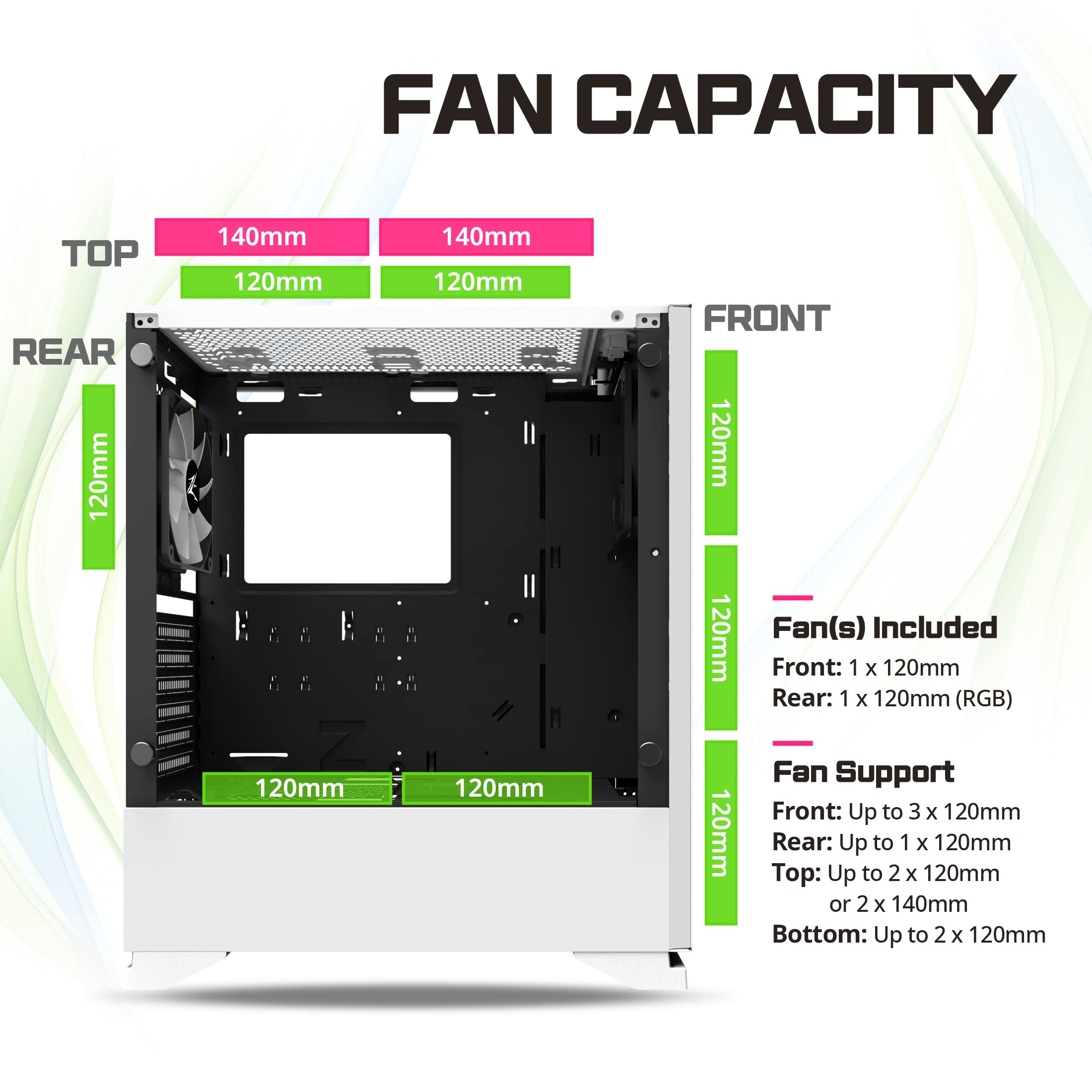
Figure 4.4: Fan Capacity
This diagram illustrates all possible fan mounting locations and sizes within the Zalman S5 case, including top, rear, front, and bottom.
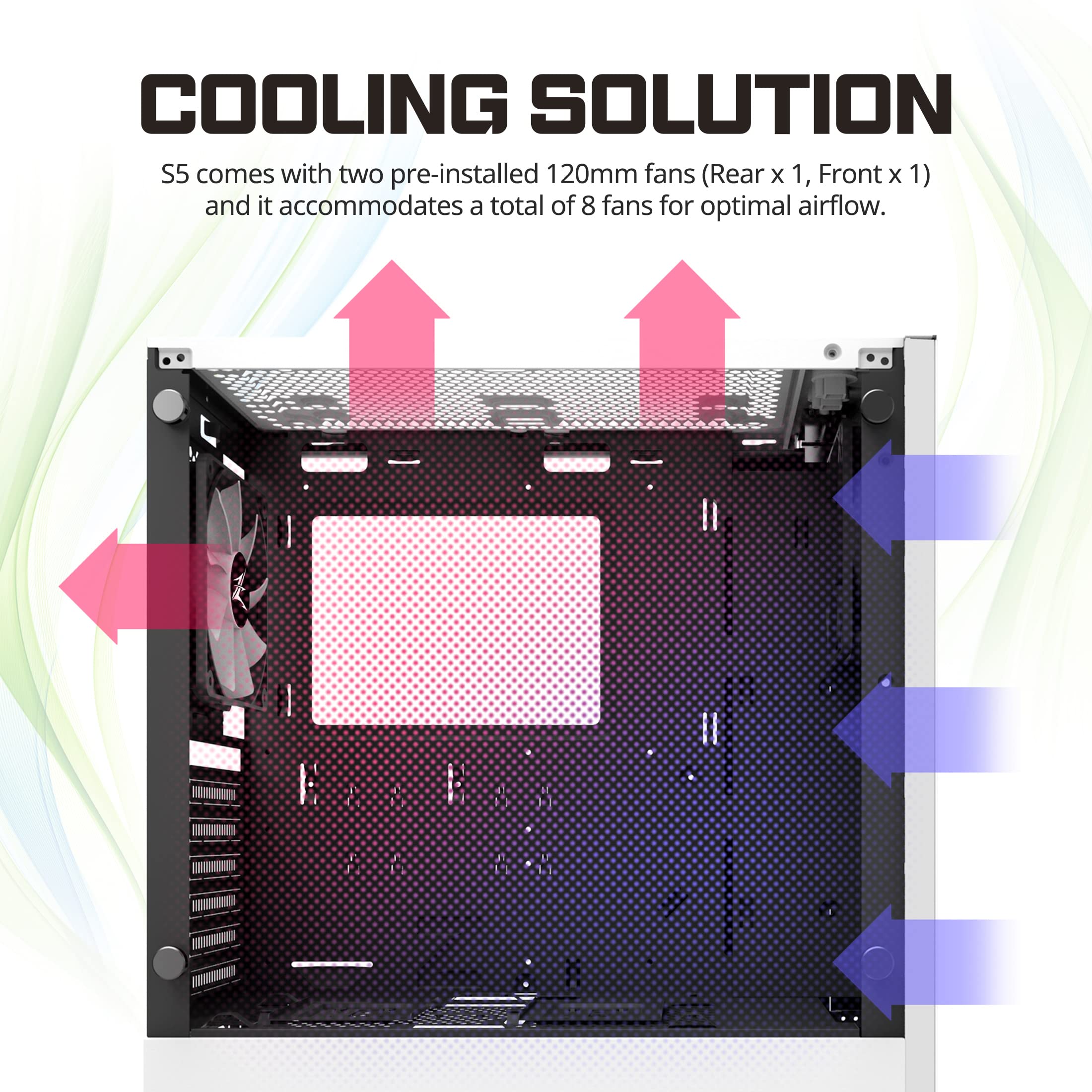
Figure 4.5: Cooling Solution Airflow
This image demonstrates the recommended airflow path within the S5 case, with cool air intake from the front and bottom, and hot air exhaust from the rear and top.

Figure 4.6: Radiator Mounting
This diagram illustrates how to mount a 240mm radiator and 120mm fans using the dedicated bracket within the case.
4.4. Front Panel I/O
The top front panel provides convenient access to essential ports and controls:
- 2 x USB 3.0 Ports
- 2 x USB 2.0 Ports
- Headphone Jack
- Microphone Jack
- HDD / Power LED Indicator
- Reset Button
- Power Button
- RGB LED Button (for controlling front panel RGB strip)
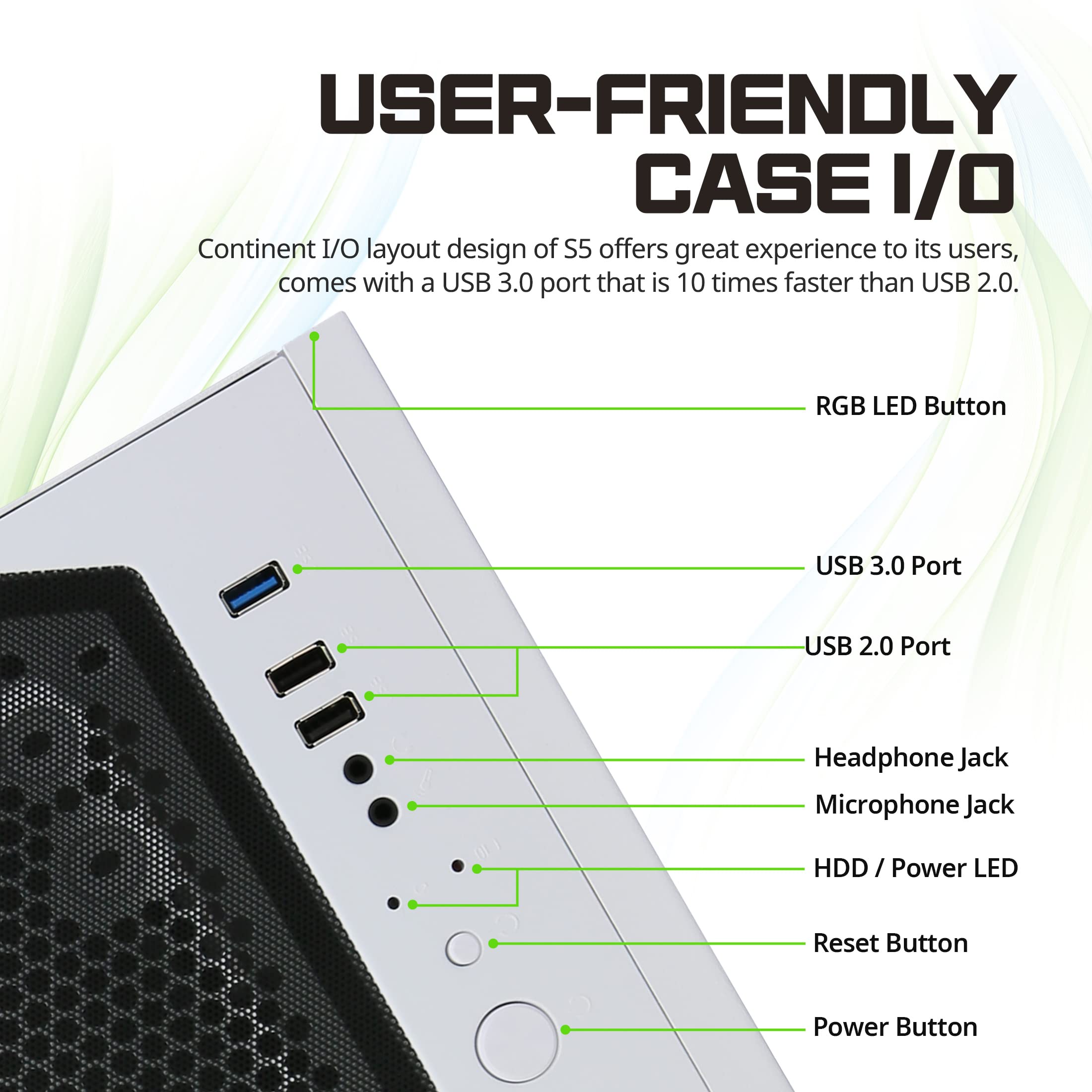
Figure 4.7: Front Panel I/O Layout
This image details the layout of the front panel input/output ports and buttons, including USB 3.0, USB 2.0, audio jacks, and control buttons for power, reset, and RGB LEDs.
5. Setup and Installation
Follow these steps for proper installation of your PC components into the Zalman S5 case.
5.1. Preparing the Case
- Carefully remove the tempered glass side panel by unscrewing the four thumb screws. Place the panel on a soft, flat surface to prevent scratches.
- Remove the rear side panel by unscrewing the two thumb screws.
5.2. Motherboard Installation
- Install the I/O shield provided with your motherboard into the rear I/O cutout of the case.
- Align your motherboard with the standoffs inside the case. Ensure the standoffs match your motherboard's form factor (ATX, Micro-ATX, or Mini-ITX).
- Secure the motherboard using the appropriate screws from the accessory kit.
5.3. Power Supply Unit (PSU) Installation
- Slide the PSU into its designated compartment at the bottom rear of the case.
- Secure the PSU to the case using screws from the accessory kit.
5.4. Drive Installation
The case supports 2x 3.5"/2.5" combo drives and 4x 2.5" SSDs.
- 3.5"/2.5" Combo Drives: Locate the drive cage at the bottom of the case. Pull out the drive trays, mount your drives, and slide the trays back into the cage.
- 2.5" SSDs: Mount 2.5" SSDs to the dedicated SSD brackets located on the motherboard tray or behind it. Secure with screws.
5.5. Graphics Card (VGA) and Expansion Card Installation
- Remove the necessary PCIe slot covers from the rear of the case.
- Insert your graphics card or other expansion cards into the appropriate PCIe slots on your motherboard.
- Secure the cards with screws.
5.6. Cable Management
Utilize the cable routing cutouts and tie-down points behind the motherboard tray to manage cables effectively. This improves airflow and aesthetics.

Figure 5.1: Cable Management Area
This image shows the dedicated space and routing options behind the motherboard tray for efficient cable management, including a hinged cover for concealing wires.
5.7. Connecting Front Panel Cables
Connect the front panel I/O cables (USB, Audio, Power SW, Reset SW, HDD LED, Power LED) to their corresponding headers on your motherboard. Refer to your motherboard manual for exact pin layouts.
Caution:
The front panel RGB lighting requires proper power connection. Ensure the IDE power connector from your PSU is inserted correctly into the RGB controller. Failure to do so may result in the RGB not functioning.

Figure 5.2: IDE Power Connector for RGB
This diagram illustrates the correct insertion of the IDE power connector from the Power Supply Unit (PSU) to power the front panel RGB lighting.
6. Operating Instructions
6.1. Powering On Your System
After all components are installed and cables are connected, replace both side panels. Connect your monitor, keyboard, mouse, and power cable to the PSU. Press the Power Button on the front panel to turn on your system.
6.2. Using Front Panel Ports
The USB 3.0 and USB 2.0 ports on the front panel provide convenient access for connecting peripherals. The headphone and microphone jacks allow for easy audio connectivity.
6.3. Controlling RGB Lighting
The front panel RGB strip can be controlled using the dedicated RGB LED Button on the top front panel. Press the button to cycle through various lighting modes and colors.
7. Maintenance
Regular maintenance helps ensure optimal performance and extends the lifespan of your PC components.
- Dust Cleaning: Periodically clean dust from the interior of the case and fan filters. Use compressed air to remove dust from fans and heatsinks.
- Fan Filters: The Zalman S5 case includes removable dust filters. Clean these filters regularly to maintain good airflow and prevent dust buildup inside the case.
- Exterior Cleaning: Wipe the exterior surfaces with a soft, damp cloth. Avoid abrasive cleaners or solvents.
8. Troubleshooting
This section addresses common issues you might encounter.
| Problem | Possible Cause | Solution |
|---|---|---|
| Front Panel RGB Not Lighting Up | IDE power connector not properly connected to the RGB controller. | Ensure the IDE power connector from the PSU is securely plugged into the RGB controller. |
| System Not Powering On | Power button cable not connected to motherboard; PSU not receiving power; PSU switch off. | Check power button cable connection to motherboard. Ensure PSU is plugged in and switched on. |
| Poor Airflow / High Temperatures | Dust buildup in filters or fans; insufficient fan configuration. | Clean dust filters and fans. Consider adding more fans or optimizing fan placement for better airflow. |
9. Specifications
| Feature | Detail |
|---|---|
| Model Name | S5 White |
| Case Type | Mid Tower |
| Motherboard Compatibility | ATX, Micro-ATX, Mini-ITX |
| Dimensions (L x W x H) | 14.84 x 7.87 x 16.93 inches |
| Item Weight | 15.4 pounds |
| Materials | Tempered Glass, Metal |
| Max CPU Cooler Height | 163mm |
| Max VGA Card Length | 340mm |
| Max PSU Length | 190mm |
| Drive Bays | 2x 3.5"/2.5" Combo, 4x 2.5" SSD |
| Pre-installed Fans | 1x 120mm (Front), 1x 120mm RGB (Rear) |
| Fan Support (Total) | Up to 8 fans |
| Radiator Support | Up to 2x 240mm (vertical mounting bracket included) |
| Front I/O Ports | 2x USB 3.0, 2x USB 2.0, Headphone, Microphone, Power, Reset, RGB LED Control |
| Light Color | RGB |
10. Warranty and Support
For warranty information and technical support, please refer to the official Zalman website or contact your local retailer. Keep your proof of purchase for warranty claims.
For further assistance, visit: www.zalman.com