
1. Introduction
This manual provides detailed instructions for the installation, configuration, and operation of the DIEWU 8-Port RS232/RS485/RS422 to Ethernet TCP/IP Converter. This industrial-grade serial device server is designed to connect multiple serial devices to an Ethernet network, supporting various communication protocols including Modbus TCP. Its compact design and robust features ensure reliable performance in diverse industrial environments.
2. Features
- 8-Port Serial Connectivity: Provides 8 independent serial ports (RS232/RS485/RS422), with individually configurable communication parameters for each port.
- Ethernet Connectivity: Dual 10/100Mbps Ethernet ports with Auto-MDI/MDIX support for flexible network integration.
- High Performance: Equipped with a 32-bit high-performance ARM processor for reliable data processing.
- Modbus TCP Support: Seamlessly integrates Modbus RTU/ASCII devices into Modbus TCP networks.
- Flexible Working Modes: Supports VCOM, TCP Server, TCP Client, and UDP operating modes.
- Customizable Baud Rate: Supports serial baud rates from 110bps to 921600bps, with five verification methods: None, Odd, Even, Mark, Space.
- Industrial Design: Rail-type, compact structure with lightning protection for enhanced durability and space-saving installation.
- Web-based Management: Built-in webpage for easy parameter setting and network firmware upgrades.

Figure 2.1: Key Features Overview
3. Physical Description
The DIEWU serial device server features a robust metal casing designed for industrial environments. It includes 8 serial ports, an Ethernet port, and power input terminals.

Figure 3.1: Front Panel Overview with Serial and Ethernet Ports

Figure 3.2: Close-up of DB9 Serial Ports
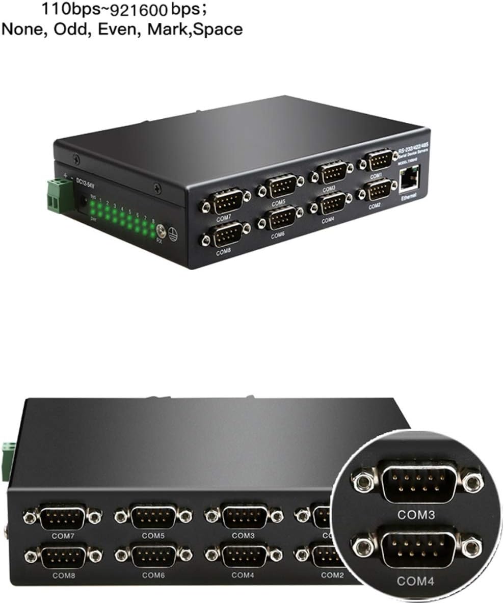
Figure 3.3: Device Top-Front View with Power and Indicators
LED Indicators
The device features several LED indicators to show its operational status:
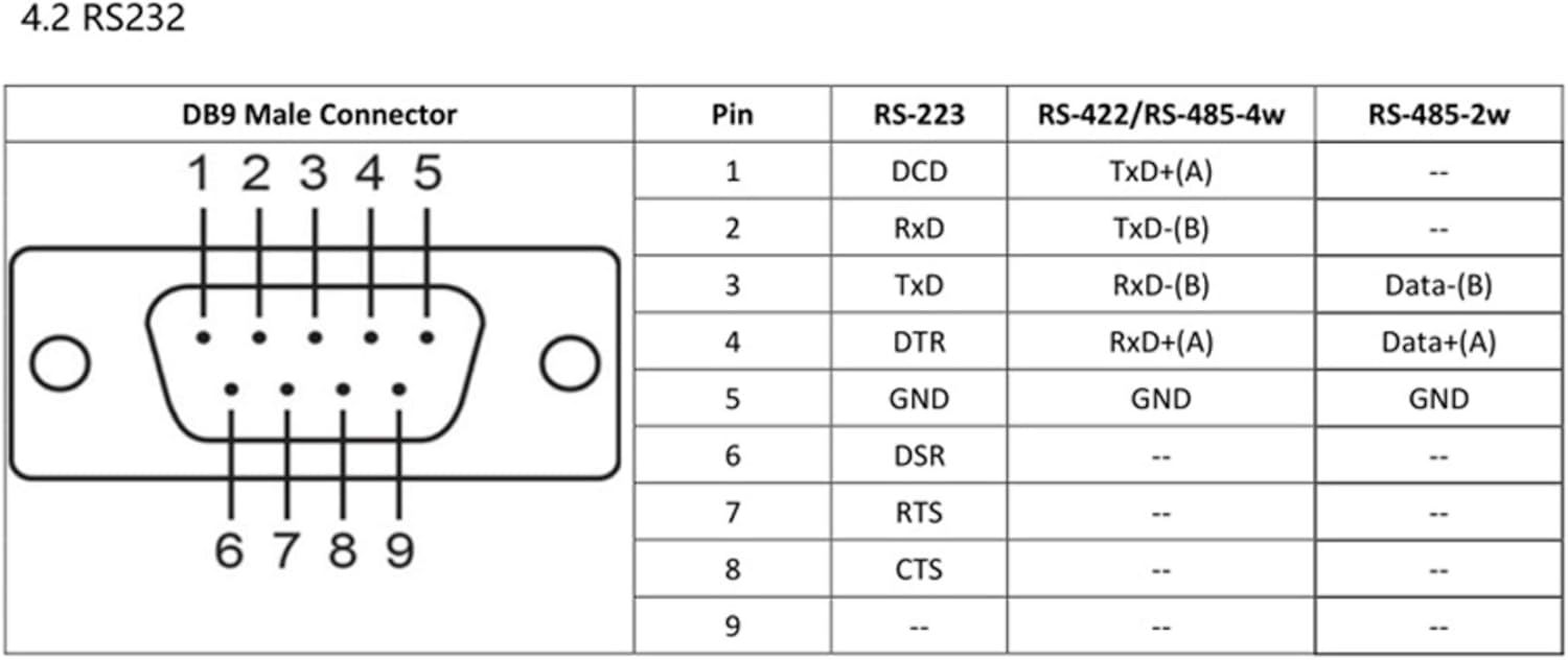
Figure 3.4: LED Indicator Status Description
- Power Indicator (Red): Illuminates when the device is powered on.
- Network Indicator (Green): Solid green when connected to the network, flashes when network data is transmitted.
- System Indicator (Green): Flashes after boot-up, indicating normal operation.
- Serial Port Indicators (Green): Flashes when transmitting or receiving serial data on the respective port.
4. Installation and Setup
4.1 Power Connection
Connect the DC12-54V power supply to the power input terminals on the device. Ensure the power source matches the specified voltage range.
4.2 Ethernet Connection
Connect an Ethernet cable from your network switch or router to the RJ45 Ethernet port on the device. The Network indicator LED should illuminate.
4.3 Serial Device Connection
Connect your RS232, RS485, or RS422 serial devices to the appropriate DB9 serial ports (COM1-COM8). Refer to the pinout diagrams in Section 6 for correct wiring.
5. Configuration
5.1 Accessing the Web Interface
The device can be configured via a web browser. By default, the device has the following network settings:
Figure 5.1: Default Device Parameters
- Ensure your computer is on the same network segment as the device (e.g., set your computer's IP to 192.168.2.x, subnet mask 255.255.255.0).
- Open a web browser and enter the default IP address: http://192.168.2.1.
- Enter the default username (admin) and password (system) to log in.
- From the web interface, you can configure network settings, serial port parameters, and operating modes.
5.2 Restoring Default Parameters
To restore the device to its factory default settings, press and hold the Reset button on the back of the device for more than 10 seconds, then release it.
6. Operating Modes
The device supports various operating modes to suit different application requirements.

Figure 6.1: TCP Server and TCP Client Operating Modes
6.1 VCOM Mode
VCOM (Virtual COM) mode allows you to map the physical serial ports of the device to virtual COM ports on a computer. This enables legacy serial applications to communicate with network-connected serial devices as if they were directly connected to the computer's serial port.
6.2 TCP Server Mode
In TCP Server mode, the serial device server listens for incoming TCP connections from client applications. Once a connection is established, data received from the serial port is sent to the connected TCP client, and data received from the TCP client is sent to the serial port.
6.3 TCP Client Mode
In TCP Client mode, the serial device server initiates a TCP connection to a specified remote TCP server. Once connected, data is transparently exchanged between the serial port and the remote TCP server.
6.4 UDP Mode
In UDP mode, the device sends and receives serial data over UDP packets. This mode is connectionless and suitable for applications where speed and broadcast capabilities are more critical than guaranteed delivery.
6.5 Modbus TCP Gateway
The device functions as a Modbus TCP gateway, converting Modbus RTU/ASCII protocols from serial devices to Modbus TCP for Ethernet communication. This allows Modbus TCP masters to communicate with Modbus RTU/ASCII slaves connected to the serial ports.

Figure 6.2: Modbus TCP IP Conversion Diagram
7. RS-232/485/422 Pinout
The DB9 male connectors on the device support RS-232, RS-422, and RS-485 standards. Refer to the following pinout diagram for correct wiring:
Figure 7.1: DB9 Male Connector Pinout
8. Specifications
Below are the technical specifications for the DIEWU 8-Port Serial Device Server:
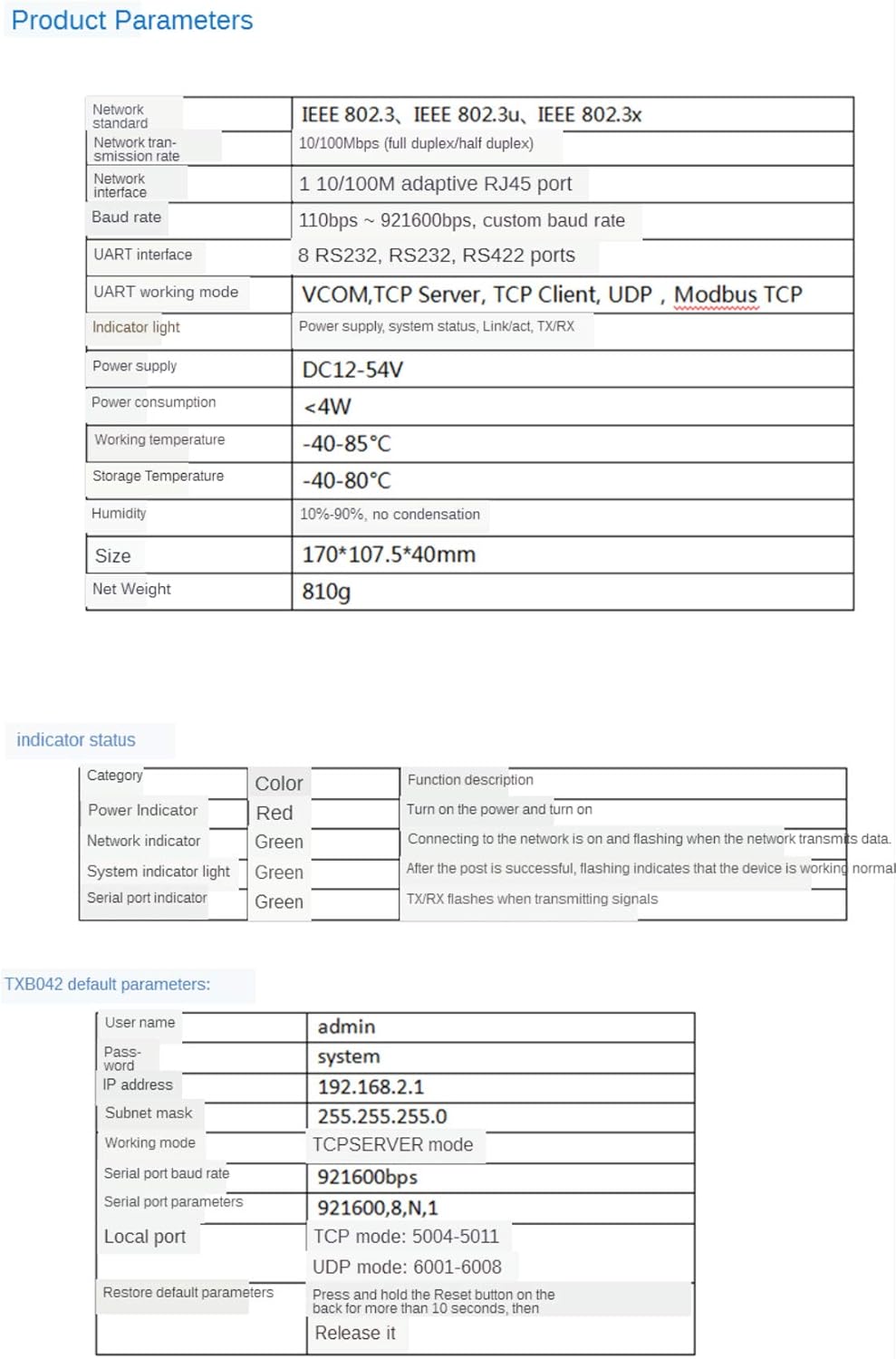
Figure 8.1: Product Parameters Table
| Parameter | Value |
|---|---|
| Brand | DIEWU |
| Model Number | N35716 |
| Number of Ports | 8 (RS232/RS485/RS422) |
| Ethernet Interface | Dual 10/100Mbps adaptive RJ45 |
| Serial Baud Rate | 110bps ~ 921600bps |
| Verification Methods | None, Odd, Even, Mark, Space |
| Working Modes | VCOM, TCP Server, TCP Client, UDP, Modbus TCP |
| Power Supply | DC12-54V |
| Power Consumption | <4W |
| Working Temperature | -40°C to 85°C |
| Storage Temperature | -40°C to 80°C |
| Humidity | 10%-90%, no condensation |
| Case Material | Metal |
| Dimensions (L*W*H) | 170 * 107.5 * 40mm |
| Net Weight | 810g |
9. Troubleshooting
- Device not powering on: Ensure the power adapter is correctly connected and providing DC12-54V. Check the power indicator LED.
- No network connection: Verify the Ethernet cable is securely connected to both the device and the network switch/router. Check the network indicator LED. Ensure your network settings (IP address, subnet mask) are compatible with the device's settings.
- Cannot access web interface: Confirm your computer's IP address is in the same subnet as the device's default IP (192.168.2.1). Try pinging the device's IP address. If still unable to access, try restoring default parameters (Section 5.2).
- Serial communication issues: Check serial port wiring according to the pinout diagram (Section 7). Verify that serial port parameters (baud rate, data bits, parity, stop bits) are correctly configured on both the device and the connected serial equipment. Ensure the correct operating mode is selected.
- Modbus communication failure: Confirm the device is in Modbus TCP mode. Verify Modbus addresses and function codes are correctly configured for both master and slave devices.
10. Warranty and Support
10.1 Warranty Information
This DIEWU product comes with a 1-year warranty from the date of purchase, covering manufacturing defects. Please retain your proof of purchase for warranty claims. The warranty does not cover damage caused by misuse, unauthorized modification, or improper installation.
10.2 Technical Support
For technical assistance, troubleshooting, or further inquiries, please contact your vendor or refer to the official DIEWU support channels. When contacting support, please provide your product model number (N35716) and a detailed description of the issue.