Introduction
The Acxico Mini Stepper Motor Driver Board is a versatile speed controller designed for 2-phase and 4-phase mini stepper motors. It operates within a DC 5V to 12V range and features multiple working modes for various applications, providing precise control over motor movement and speed.
Setup Instructions
Before operating the Acxico Mini Stepper Motor Driver Board, follow these steps for proper setup and connection.
Component Overview

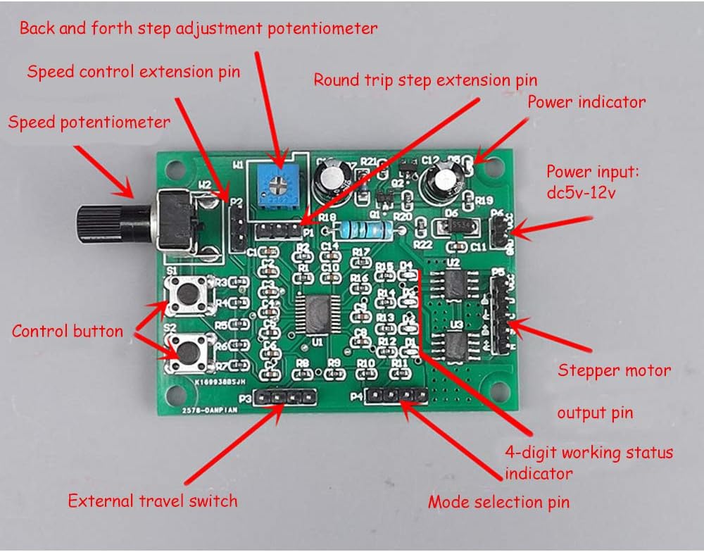
This image provides an overview of the Acxico Mini Stepper Motor Driver Board, highlighting key components such as the power input, stepper motor output, control buttons (S1, S2), speed adjustment potentiometer (W2), automatic round-trip step adjustment potentiometer (W1), external travel switch pin (P3), and mode selection pins (P4).
Power Connection
Connect a DC 5V to 12V power supply to the P6 power input pin. Ensure correct polarity: the positive electrode connects to the '+' terminal and the negative pole connects to the '-' terminal. Incorrect polarity can damage the board.
Motor Connection
The board supports both 2-phase 4-wire and 4-phase 5-wire stepper motors. Connect your stepper motor to the P5 output pin. It is crucial to refer to your specific motor's specifications for correct wiring. Please note that many standard 4-wire stepper motors use an A+, A-, B+, B- wiring sequence, which may require re-pinning your motor connector to match the board's A+, B+, A-, B- configuration for proper operation.

This image illustrates the correct connection points for the stepper motor (P5) and the DC 5V-12V power supply (P6), indicating the positive and negative terminals.
External Travel Switch Connection
For applications requiring limit stops or automatic reciprocating motion, connect external micro switches to the P3 pin. These switches will define the travel limits for the motor's movement.

This image demonstrates how to connect external micro switches to the P3 pin, enabling the implementation of travel limits for the stepper motor.
Mode Selection
The board offers four distinct working modes. Select the desired mode by placing jumpers on the mode selection pins (P4). Refer to the 'Operating Modes' section for a detailed explanation of each mode and its corresponding jumper configuration.

This image displays the various jumper settings on the P4 pins to select between Working Mode 1, Working Mode 2, Working Mode 3, and Working Mode 4.
Operating Modes
The Acxico Mini Stepper Motor Driver Board features four operational modes, each suited for different control requirements.
1. Normal Mode 1
In this mode, the S1 button functions as a start/stop control, and the S2 button controls the forward and reverse direction. The W2 potentiometer adjusts the motor speed. If limit reversal is required, two limit switches can be connected to the P3 pin. The motor motion shaft should be equipped with contacts, allowing the motor to reciprocate within the stroke defined by the two limit switches.
2. Normal Mode 2
S1 acts as the forward start button, and S2 acts as the reverse start button. Pressing either button will initiate movement, and pressing any button again will stop the motor. The W2 potentiometer regulates the motor speed. If a limit stop is required, two limit switches can be connected to the P3 pin. The motor will stop upon touching a limit switch and will reverse direction after the opposite button is pressed.
3. Jog Mode
In Jog Mode, pressing and holding S1 causes forward rotation, and releasing it stops the motor. Similarly, pressing and holding S2 causes reverse rotation, and releasing it stops the motor. The W2 potentiometer adjusts the speed. If a limit stop is required, an upper limit switch can be connected to P3.
4. Automatic Round-trip Mode
S1 controls the start and stop of the operation, while S2 controls the reverse direction. The W2 potentiometer adjusts the motor speed, and the W1 potentiometer adjusts the number of steps for the automatic round-trip. After starting, the motor automatically runs back and forth within the number of steps adjusted by W1.
Speed and Step Adjustment
The board features two potentiometers for fine-tuning motor behavior:
- W2 Potentiometer (Speed Control): Turning W2 clockwise increases the motor speed. The speed can be adjusted across a wide range, from 0.32 steps/second to 800 steps/second, depending on the P2 pin configuration.
- W1 Potentiometer (Automatic Round-trip Step Adjustment): Used in Automatic Round-trip Mode, turning W1 clockwise increases the number of steps for the round-trip motion. The adjustment range for W1 is typically 1-200 steps for short strokes and 200-1200 steps for long strokes.

This image details the W1 and W2 potentiometers, showing their functions for adjusting automatic round-trip steps and motor speed, respectively, along with their typical adjustment ranges.
This image provides a closer look at the W2 speed adjustment potentiometer and the P2 pin, demonstrating how to select between slow and fast speed adjustment ranges.
Maintenance
To ensure the longevity and optimal performance of your Acxico Mini Stepper Motor Driver Board, observe the following maintenance guidelines:
- Keep Clean and Dry: Protect the board from dust, dirt, and moisture. Operate it in a clean, dry environment.
- Proper Ventilation: Ensure adequate airflow around the board to prevent overheating, especially during extended operation.
- Voltage Adherence: Always operate the board within its specified DC 5V-12V voltage range. Exceeding this range can cause permanent damage.
- Avoid Short Circuits: Exercise caution during wiring to prevent accidental short circuits, which can damage the board and connected components.
Troubleshooting
If you encounter issues with your Acxico Mini Stepper Motor Driver Board, consider the following common problems and solutions:
- Motor not working after connection:
Issue: The stepper motor does not move or operates erratically after being connected.
Solution: Verify your motor's wiring. The board's P5 output pins are typically configured for A+, B+, A-, B-. Many 4-wire stepper motors use an A+, A-, B+, B- sequence. You may need to re-pin your motor connector to match the board's specific configuration. Consult your motor's datasheet for its wiring diagram. - LEDs blink, but motor does not move (when using a buck converter):
Issue: When powered via a buck converter, the board's indicator LEDs might blink, but the motor remains unresponsive.
Solution: Ensure the buck converter provides a stable power output within the 5V-12V range and can supply sufficient current (rated 800mA). Some buck converters may introduce electrical noise or voltage fluctuations that interfere with the driver board's sensitive operation. Try powering the board directly from a stable DC power supply within the specified voltage range to rule out the buck converter as the cause. - Motor lacks power or does not move larger motors (e.g., NEMA17):
Issue: The board struggles to drive larger stepper motors, resulting in low torque or no movement.
Solution: This driver board is designed for mini stepper motors with a rated current of 800mA. Larger motors, such as NEMA17, often require significantly more current than this board can provide. Attempting to drive them with this board may result in insufficient torque or complete failure to operate. Verify your motor's current requirements and ensure they are compatible with the board's 800mA rating.
Specifications
| Voltage Range | DC 5V ~ 12V |
| Rated Current | 800mA |
| Dimensions (L x W) | 59.3mm x 43.6mm |
| Protections | Power Reverse Connection Protection, Over-current Protection, Overheat Protection |
| Material | Copper |
| Item Weight | 0.88 ounces |
| Model Number | LB261 |
Warranty Information
This Acxico product comes with a standard manufacturer's warranty against defects in materials and workmanship. For specific warranty terms, duration, or to make a warranty claim, please retain your proof of purchase and contact your retailer or the manufacturer directly. Warranty coverage typically does not include damage caused by misuse, improper installation, or exceeding specified operating conditions.
Customer Support
For technical assistance, troubleshooting guidance, or any further inquiries regarding your Acxico Mini Stepper Motor Driver Board, please contact the seller through your purchase platform. You may also refer to the manufacturer's official website for additional resources or contact information.