1. Introduction
The Acegmet JXM8000 is a True RMS (TRMS) digital multimeter designed for accurate and reliable electrical measurements. It features both automatic and manual ranging capabilities, allowing for versatile use in various applications. This manual provides essential information for the safe and effective operation, maintenance, and troubleshooting of your device.
2. Safety Information
Always adhere to safety precautions when using electrical testing equipment. Failure to do so may result in electric shock, injury, or damage to the multimeter or equipment under test.
- Overload Protection: The multimeter is equipped with overload protection. When the input voltage is below 250V, the device automatically prevents burnout.
- Fuse Disconnect Function: In case of excessive current, the internal fuses will blow to protect the multimeter's internal circuitry. If a fuse blows, the screen will display "FUSE" and an alarm will sound.
- Wrong Polarity Alarm: If the test leads are connected to ports that do not match the selected measurement function (gear position), the screen will display "LEAD" and emit an audible beep. Correct the lead connection immediately.
- Ensure the multimeter's safety class (IEC61010 CAT.600V CAT IV, 1000V CAT.III) is appropriate for the measurement task.
- Do not attempt to measure voltages or currents exceeding the specified maximum limits.
- Inspect test leads for damage before each use. Replace damaged leads immediately.
- Do not operate the multimeter if it appears damaged or is not functioning correctly.
3. Product Overview
The Acegmet JXM8000 Digital Multimeter features a robust design with a clear display and intuitive controls.
3.1 Components and Controls
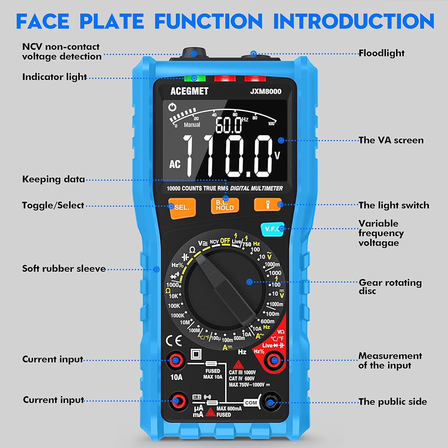
Figure 3.1: Front view of the Acegmet JXM8000 Digital Multimeter with labeled components.
- VA Screen: Large LCD display for measurement readings, units, and indicators.
- Indicator Light: Provides visual feedback for certain functions, such as NCV.
- Flashlight: Located at the top, activated by the light switch for illumination in dark areas.
- SEL. Button (Toggle/Select): Used to switch between different measurement modes within a single rotary switch position (e.g., AC/DC, Diode/Continuity).
- HOLD Button (Keeping Data): Freezes the current reading on the display. Press again to release.
- V.F.C Button (Variable Frequency Voltage): Activates the Variable Frequency Control measurement mode.
- Gear Rotating Disc: The central rotary switch used to select the desired measurement function.
- Input Jacks: Ports for connecting test leads. These include common (COM), voltage/resistance/frequency/capacitance (VΩHznF), and current (mA/10A) inputs.
- Soft Rubber Sleeve: A protective outer casing designed to prevent accidental electric shock and provide durability.
3.2 Key Features
- True RMS (TRMS): Accurately measures AC voltage and current for non-sine wave signals.
- Auto/Manual Ranging: Offers flexibility for both automatic range selection and manual range control.
- Non-Contact Voltage (NCV) Detection: Detects AC voltage without physical contact.
- Live Line Test: Identifies live wires.
- Temperature Measurement: Measures temperature in both Celsius and Fahrenheit.
- 10000 Counts Display: Provides high-resolution readings.
- Data Hold: Freezes the displayed measurement.
- Auto Shut-down: Automatically powers off after 15 minutes of inactivity to conserve battery life.
- Low Battery Indication: Alerts when batteries need replacement.
4. Setup
4.1 Battery Installation
The multimeter requires 2 x AA 1.5V batteries. To install or replace batteries:
- Ensure the multimeter is powered off and test leads are disconnected.
- Carefully remove the soft rubber sleeve.
- Locate the battery compartment cover on the back of the device.
- Unscrew the retaining screw(s) and remove the cover.
- Insert the 2 x AA batteries, observing correct polarity (+/-).
- Replace the battery compartment cover and secure it with the screw(s).
- Reinstall the soft rubber sleeve.
4.2 Connecting Test Leads
Always connect the black test lead to the "COM" (Common) jack. Connect the red test lead to the appropriate input jack based on the desired measurement:
- For Voltage, Resistance, Frequency, Capacitance, Diode, and Continuity measurements, connect the red lead to the "VΩHznF" jack.
- For Current measurements (up to 600mA), connect the red lead to the "mA" jack.
- For High Current measurements (up to 10A), connect the red lead to the "10A" jack.
Ensure test leads are fully inserted into the jacks before taking measurements.
5. Operating Instructions
5.1 Power On/Off
To power on the multimeter, rotate the gear rotating disc from the "OFF" position to any desired measurement function. To power off, rotate the disc back to the "OFF" position.
5.2 Automatic and Manual Ranging

Figure 5.1: Rotary switch indicating Automatic and Manual Ranging sections.
- Automatic Range Function: When the rotary switch is set to the "AUTOMATIC RANGE" section, the multimeter automatically selects the appropriate measurement range for AC/DC voltage, resistance, capacitance, frequency, on/off (continuity), and diode tests. This simplifies operation.
- Manual Range Function: When the rotary switch is set to the "MANUAL RANGE" section, you can manually select specific ranges for NCV, Live wire identification, AC/DC voltage, AC/DC current, temperature, and resistance measurements. This provides greater control for experienced users.
5.3 Specific Measurements
Follow these general steps for most measurements:
- Connect test leads correctly as described in Section 4.2.
- Rotate the gear rotating disc to the desired measurement function.
- If multiple functions are available at one position (e.g., AC/DC voltage), press the "SEL." button to toggle between them.
- Apply the test leads to the circuit or component under test.
- Read the measurement value on the VA screen.
5.3.1 Voltage Measurement (AC/DC)
Set the rotary switch to the 'V' (Voltage) position. Use the 'SEL.' button to switch between AC (~) and DC ( ) voltage. Connect test leads in parallel with the circuit or component.
5.3.2 Current Measurement (AC/DC)
Set the rotary switch to the 'A' (Current) position. Use the 'SEL.' button to switch between AC (~) and DC ( ) current. Connect test leads in series with the circuit. Ensure the correct input jack (mA or 10A) is used.
5.3.3 Resistance Measurement (Ω)
Set the rotary switch to the 'Ω' (Resistance) position. Connect test leads across the component. Ensure the circuit is de-energized before measuring resistance.
5.3.4 Continuity Test
Set the rotary switch to the 'Ω' (Resistance) position and press 'SEL.' until the continuity symbol ( ) is displayed. A continuous beep indicates a low-resistance path (continuity).
5.3.5 Diode Test
Set the rotary switch to the 'Ω' (Resistance) position and press 'SEL.' until the diode symbol ( ) is displayed. Connect the red lead to the anode and the black lead to the cathode of the diode. The forward voltage drop will be displayed.
5.3.6 Capacitance Measurement (nF/µF/mF)
Set the rotary switch to the 'nF' (Capacitance) position. Connect test leads across the capacitor. Ensure the capacitor is discharged before testing.
5.3.7 Frequency Measurement (Hz)
Set the rotary switch to the 'Hz' (Frequency) position. Connect test leads to the signal source.
5.3.8 Temperature Measurement (°C/°F)

Figure 5.2: Multimeter demonstrating NCV, Live Line, and Temperature testing functions.
Set the rotary switch to the '°C/°F' (Temperature) position. Connect the included K-type thermocouple probe to the input jacks (usually VΩHznF and COM). Place the probe tip on or near the object whose temperature is to be measured. Press 'SEL.' to switch between Celsius and Fahrenheit.
5.3.9 Non-Contact Voltage (NCV) Detection
Set the rotary switch to the 'NCV' position. Move the top of the multimeter near an AC voltage source. The indicator light will flash, and an audible beep will sound, with the frequency of beeps increasing as the multimeter gets closer to the voltage source.
5.3.10 Live Line Test
Set the rotary switch to the 'Live' position. Insert the red test lead into the 'VΩHznF' jack. Touch the red test lead to the conductor to be tested. The display will indicate 'LIVE' and an audible alarm will sound if a live wire is detected.
5.4 Data Hold Function
Press the "HOLD" button to freeze the current reading on the display. Press it again to release the hold function and resume live readings.
5.5 Backlight and Flashlight
Press the light switch button (often integrated with the HOLD button or a separate button) to turn on the display backlight for better visibility in low-light conditions. A long press may activate the flashlight located at the top of the multimeter.
6. Maintenance
6.1 Cleaning
Wipe the multimeter casing with a damp cloth and mild detergent. Do not use abrasive cleaners or solvents. Ensure the device is powered off and disconnected from all circuits before cleaning.
6.2 Battery Replacement
When the low battery indicator appears on the display, replace the batteries as described in Section 4.1. Remove batteries if the multimeter will not be used for an extended period.
6.3 Fuse Replacement

Figure 6.1: Internal view highlighting fuse protection.
If a fuse blows (indicated by "FUSE" on the display and an alarm), it must be replaced with a fuse of the same type and rating. The JXM8000 uses fast-blow ceramic fuses. Refer to the specifications for correct fuse ratings.
- Ensure the multimeter is powered off and all test leads are disconnected.
- Carefully remove the soft rubber sleeve.
- Unscrew the screws securing the back casing and carefully open the multimeter.
- Locate the blown fuse(s) and gently remove them.
- Install new fuses of the correct type and rating.
- Carefully reassemble the multimeter, ensuring all screws are tightened.
- Reinstall the soft rubber sleeve.
6.4 Storage
Store the multimeter in a cool, dry place, away from direct sunlight and extreme temperatures. If storing for an extended period, remove the batteries.
7. Troubleshooting
- Display shows "LEAD" and beeps: This indicates incorrect test lead connection for the selected function. Reconnect the test leads to the appropriate input jacks.
- Display shows "OL": This indicates an overload condition, meaning the measured value exceeds the selected range or the multimeter's maximum capacity. Switch to a higher range (if in manual mode) or ensure the measurement is within the device's limits.
- Multimeter does not power on: Check battery installation and ensure batteries are not depleted. Replace if necessary.
- Inaccurate readings: Check battery level, ensure test leads are properly connected, and verify the correct measurement function and range are selected. Clean test lead tips if corroded.
- No continuity beep: Ensure the circuit is de-energized. Check test leads for damage.
8. Specifications
| Parameter | Specification |
|---|---|
| Max Display | 9999 counts |
| Range Selection | Automatic & Manual Range |
| Measurement Speed | 10 times/second |
| Overload Display | Display OL |
| Wrong Insert Alarm | Display LEAD |
| On-off Test | Buzzer |
| NCV/VFC Function | Yes |
| Live Line Test | Yes |
| Data Hold Function | Yes |
| Low Battery Indication | Yes |
| Auto Shut-down | 15 minutes |
| Power Supply | 2 x AA 1.5V Batteries |
| Safety Class | IEC61010 CAT.600V CAT IV, 1000V CAT.III |
| AC Current Range | 99.99mA/600mA ±(1.0% + 3); 10A (1.5% + 3) |
| AC Voltage Range | 999.9mV/9.999V/99.99V ± (0.8%+3); 750V ± (1.0%+5) |
| DC Voltage Range | 999.9mV/9.999V/99.99V/999.9V ± (0.5%+3) |
| DC Current Range | 99.99µA/999.9mA/600mA ±(0.8% + 3); 10A (1.2% + 3) |
| Resistance Range | 999.9Ω/9.999KΩ/99.99KΩ/999.9KΩ/9.999MΩ ± (0.8%+32); 99.99MΩ ± (1.2%+5) |
| Capacitance Range | 9.999nF ±(4.0% + 30); 99.99nF/999.9nF/9.999µF/99.99µF/999.9µF/9.999mF/99.99mF ±(4.0% + 3) |
| Frequency Range | 9.999Hz/99.99Hz/999.9Hz/9.999kHz/99.99kHz/999.9kHz/9.999MHz ±(1.0%+3) |
| Temperature Range | -4℉-1832℉ / -20℃-1000℃ ±(1.0%+3) |
9. Warranty and Support
The Acegmet JXM8000 Digital Multimeter comes with an 18-month warranty from the date of purchase. This warranty covers defects in materials and workmanship under normal use. It does not cover damage caused by misuse, accident, unauthorized modification, or neglect.
For technical support, warranty claims, or service inquiries, please contact Acegmet customer service through the retailer's platform or the official Acegmet website. Please have your purchase receipt and product model number (JXM8000) available when contacting support.