1. Introduction
This manual provides detailed instructions for the DONGKER PWM Driver Module, a 4-wire fan temperature controller designed for industrial applications. It supports wide voltage operation (DC 11V-55V) and features a digital display for monitoring fan speed and temperature. The module is compatible with EC 4-wire fans, supports low-temperature fan shutdown, reverse sequence fans, and EBM 4-wire fans.

Image 1: DONGKER PWM Driver Module with included NTC temperature sensor.
2. Features
- PWM 4-wire fan temperature control for industrial fans.
- Wide voltage operation: DC 11V to 55V.
- Digital display for fan speed and temperature.
- Supports EC 4-wire fan control.
- Supports low-temperature fan shutdown.
- Supports reverse sequence fans.
- Supports EBM 4-wire fans.
3. Product Overview and Interface Introduction
Familiarize yourself with the components and connection points of the PWM driver module.
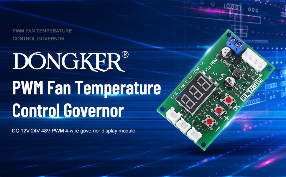
Image 2: Labeled diagram of the DONGKER PWM Driver Module showing all interfaces and controls.
Interface Descriptions:
- Power Interface (DC 11V-55V): Main power input for the control board and connected fans.
- Fan Interface (4-pin): Output for connecting the 4-wire fan. Includes Fan +, Fan -, Temperature Sense, and PWM output.
- Temperature Probe Interface (2-pin): Connects the NTC probe (parameter 10K B=3950) for temperature measurement.
- Alarm Signal Port (WORK): Outputs a high level during normal operation and a low level if the fan is abnormal.
- Relay Interface (RELAY): Expansion interface to drive a 9V or 12V relay. This can control an external fan's power line, opening the relay when fan control stops.
Control Buttons:
- '+' and '-' Buttons: Used to switch display modes and adjust parameter values. Short-press to change display, long-press for rapid adjustment during setting.
- 'OK' Button: Used to enter and save parameter settings.
4. Specifications
| Parameter | Value |
|---|---|
| Product Name | PWM 4-Wire Fan Temperature Controller |
| Working Voltage | DC 11V ~ 55V |
| Working Current | 0.1A (MAX) |
| Fan Current | 5A (MAX) |
| PWM Range | 5% ~ 100% or 0% |
| PWM Frequency | 20KHz / 2.5KHz |
| PWM Signal Amplitude | 10.5V (no load) |
| Temperature Measurement Range | -9.9°C ~ 99.9°C |
| Working Temperature | -25°C ~ 85°C |
| Working Humidity | 5% ~ 95% RH |
| Sensor Wire Length | 1 meter |
| Dimensions | 70.5 x 40.5 x 13.5mm (2.78"L x 1.59"W x 0.53"H) |
| Item Weight | 0.986 ounces (0.03 Kilograms) |
| Material | Copper |

Image 3: Physical dimensions of the DONGKER PWM Driver Module.
5. Setup and Connection
Follow these steps to correctly set up your DONGKER PWM Driver Module:
- Power Connection: Connect your DC power supply (11V-55V) to the main power input interface. Ensure correct polarity. This power supplies both the control board and the fan.
- Fan Connection: Connect your 4-wire fan to the Fan output interface. Ensure the PWM signal wire is correctly connected.
- Temperature Probe Connection: Connect the NTC temperature probe (10K B=3950) to the dedicated 2-pin temperature probe interface. Position the probe to accurately measure the desired temperature.
- Optional: Alarm Signal Port: If an alarm signal is required, connect external monitoring equipment to the Alarm Signal Port (WORK).
- Optional: Relay Connection: For controlling additional fans or devices, connect a 9V or 12V relay to the Relay interface. This allows the module to switch external power based on fan control status.
Important Note: The fan interface on this module is designed for industrial fans and may differ from standard PC chassis fan connectors. Direct shutdown functionality only applies to fans with a signal shutdown feature (fan stops when speed control line is grounded). For other fan types, external relay control may be necessary to force power off.
6. Operation and Parameter Settings
6.1. Basic Operation
Once powered on, the digital display will show either the fan speed (X10 RPM) or the measured temperature (°C). Use the '+' and '-' buttons to switch between these display modes.
6.2. Setting PWM Output (Quick Adjustment)
- With the PCB powered ON, short-press the 'OK' button.
- The display will show the current inherent PWM output percentage (range: 5% ~ 100%).
- Use the '+' and '-' buttons to adjust the PWM percentage.
- Short-press 'OK' again to save the setting and exit.
6.3. Setting Temperature Parameters (L, H, C)
These parameters define the fan's behavior based on temperature.
- With the PCB powered ON, long-press the 'OK' button to enter temperature parameter setting mode.
- The display will show "L__" (Acceleration Temperature). Use '+' and '-' to adjust the value (range: 5°C ~ 94°C).
- Short-press 'OK' to save "L__" and move to "H__" (Full Speed Temperature). Adjust with '+' and '-' (range: 10°C ~ 99°C).
- Short-press 'OK' to save "H__" and move to "C__" (Shut-down Temperature). Adjust with '+' and '-' (range: 0°C ~ 92°C).
- Short-press 'OK' to save "C__" and exit the temperature parameter adjustment mode.
Parameter Relationship: The difference between Acceleration Temperature (L) and Full Speed Temperature (H) must be at least 5°C. The difference between Shut-down Temperature (C) and Acceleration Temperature (L) must be at least 2°C. The module will automatically adjust other parameters if these conditions are violated during setting.
6.4. Setting Function Parameters (F, P)
These settings control PWM frequency and direction.
- With the PCB powered OFF, press and hold the 'OK' button while powering ON the module. Continue holding until "F__" appears.
- The display will show "F20" or "F2.5" (PWM Frequency). Use '+' and '-' to select between 20KHz and 2.5KHz.
- Short-press 'OK' to save the frequency and move to "P__" (PWM Output Direction). The display will show "P1" (forward) or "P-1" (reverse). Adjust with '+' and '-'.
- Short-press 'OK' again to save and exit.
7. Explanation of Temperature Parameters
- Acceleration Temperature (L**): (Range: 5°C ~ 94°C) When the measured temperature exceeds this value, the PWM output begins to increase proportionally with the temperature rise, speeding up the fan.
- Full Speed Temperature (H**): (Range: 10°C ~ 99°C) When the measured temperature reaches or exceeds this value, the PWM output will be 100%, causing the fan to run at its maximum speed.
- Shut-down Temperature (C**): (Range: 0°C ~ 92°C) This enables the low-temperature shutdown function. If set to a value greater than 0, the fan will turn off (PWM signal and extended relay output cease) when the temperature drops below this value. The fan will restart and adjust speed when the temperature rises above the Acceleration Temperature (L). If set to 0, the low-temperature shutdown function is disabled, and the PWM and relay outputs will always be active.
8. Display Indicators
- "X10 RPM" Indicator: When this light is on, the digital display shows the fan speed. The displayed value is the actual RPM divided by 10. For example, if "256" is displayed, the actual fan speed is 2560 RPM.
- "°C" Indicator: When this light is on, the digital display shows the current temperature measured by the NTC probe in degrees Celsius.
- "RUN" Indicator: This light illuminates when the fan is actively controlled to run and turns off when the fan is commanded to stop. Note that this indicates the control state, not necessarily the physical state of the fan. If the fan fails while the "RUN" light is on, the alarm signal port will output a low level.
9. Troubleshooting
- Fan Not Shutting Down: Ensure your fan supports signal shutdown (fan stops when speed control line is grounded). If not, use the relay interface with an external relay to cut power to the fan.
- Incorrect Fan Speed Display: Verify the fan's tachometer signal is correctly connected. Some fans may not provide a compatible RPM signal.
- Fan Not Responding to PWM: Check the PWM frequency setting (F20/F2.5) to match your fan's requirements. Also, ensure the PWM output direction (P1/P-1) is correct for your fan type (e.g., EBM fans may require specific settings).
- No Display or Power: Confirm the power input (DC 11V-55V) is correctly connected and within the specified voltage range. Check for proper polarity.
- Temperature Reading Inaccurate: Ensure the NTC temperature probe is securely connected and positioned correctly to measure the desired temperature.
- Connector Compatibility: The 4-pin fan connector on this module is designed for industrial fans and may not be compatible with standard PC 4-pin fan connectors. Adapters or custom wiring may be required.
10. Package Contents
- 1x DONGKER PWM 4-Wire Fan Temperature Controller Module
- 1x NTC Temperature Sensor
11. Warranty and Support
For technical support or warranty inquiries, please contact DONGKER customer service through your purchase platform. Please refer to your purchase documentation for specific warranty terms and conditions.


