1. Introduction
The Taidacent Uart CAN Converter (Model 3BT11) is a compact, high-performance, and stable module designed for transparent data conversion between serial (TTL, RS232, RS485) and CAN bus interfaces. It facilitates seamless communication between serial devices and CAN devices, offering flexible configuration and reliable operation.
2. Features
- Small and exquisite design, ensuring high performance and stability.
- Equipped with one TTL interface and one CAN interface.
- Supports serial port baud rates from 1200 bps to 460800 bps.
- Supports CAN bus baud rates from 10 kbps to 1000 kbps.
- Firmware upgradeable via the TTL interface for convenient customization.
- Achieves two-way data communication between CAN and TTL.
- Features electrostatic protection, surge protection, and excellent EMC performance on the CAN interface.
- Includes 14 sets of configurable filters for CAN messages.
- Offers three working modes: transparent conversion, transparent conversion with logo, and format conversion.
- Supports offline detection and automatic recovery.
- Complies with CAN2.0B specification and is compatible with CAN2.0A, meeting ISO11898-1/2/3 standards.
- CAN buffer capacity of up to 1000 frames to prevent data loss.
- High-speed conversion: up to 1270 extended frames/second at 115200 bps serial and 250 kbps CAN; over 5000 extended frames/second at 460800 bps serial and 1000 kbps CAN.
3. Hardware Overview
The Taidacent Uart CAN Converter is a compact module with clearly labeled interfaces for easy integration.
3.1 Module Layout

Figure 1: Top view of the converter module. This image displays the main components, including the microcontroller and other surface-mounted devices, along with the various solder pads for connections.
3.2 Dimensions
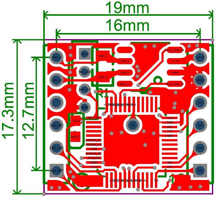
Figure 2: Bottom view of the converter module with physical dimensions. The module measures approximately 19mm by 17.3mm, with the main PCB area being 16mm by 12.7mm.
3.3 Pinout Diagram
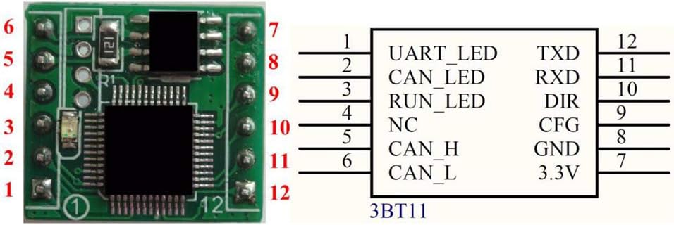
Figure 3: Pinout diagram for the 3BT11 module. This diagram illustrates the function of each of the 12 pins on the converter.
| Pin No. | Label | Description |
|---|---|---|
| 1 | UART_LED | UART Status Indicator LED |
| 2 | CAN_LED | CAN Status Indicator LED |
| 3 | RUN_LED | Module Running Status Indicator LED |
| 4 | NC | No Connection |
| 5 | CAN_H | CAN High-level Signal |
| 6 | CAN_L | CAN Low-level Signal |
| 7 | 3.3V | Power Input (3.3V) |
| 8 | GND | Ground |
| 9 | CFG | Configuration Pin |
| 10 | DIR | Direction Control (for RS485, if applicable) |
| 11 | RXD | UART Receive Data |
| 12 | TXD | UART Transmit Data |
4. Setup
Follow these steps to set up your Taidacent Uart CAN Converter:
4.1 Power Connection
- Connect a stable 3.3V DC power supply to Pin 7 (3.3V) and Pin 8 (GND).
- Ensure the power supply meets the module's requirements (3.3V@40mA).
4.2 Data Connections
- UART Connection: Connect your serial device's TXD to Pin 11 (RXD) and RXD to Pin 12 (TXD) of the converter. Ensure common ground connection.
- CAN Bus Connection: Connect the CAN_H line of your CAN bus to Pin 5 (CAN_H) and the CAN_L line to Pin 6 (CAN_L).
- For RS485 communication, connect the DIR pin (Pin 10) to control the data direction, if required by your setup.
5. Operating Instructions
The converter operates based on its configured mode. Configuration is typically done via a dedicated software tool through the serial interface.
5.1 Software Configuration
The module's operating parameters, such as serial baud rate, CAN baud rate, conversion mode, and filters, are set using a configuration tool. The following images illustrate the typical interface of such a tool.
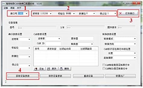
Figure 4: Initial software configuration interface. This screen allows selection of the serial port (COM port), baud rate, parity, data bits, and stop bits. It also provides options to open/close the port and retrieve device information.
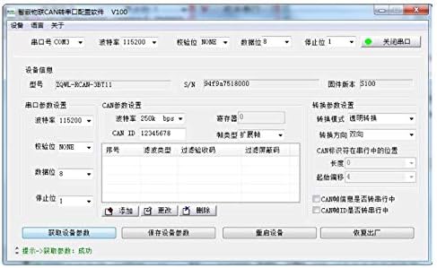
Figure 5: Detailed software configuration interface. This screen displays device information (model, S/N, firmware version) and allows configuration of CAN parameters (baud rate, CAN ID), conversion settings (mode, direction), and message filters. Buttons for retrieving, saving, resetting, and restoring factory settings are also present.
- Connect to Device: Open the configuration software, select the correct serial port (COM port) connected to the converter's TTL interface, and set the serial baud rate. Click to open the port.
- Retrieve Settings: Use the software to read the current configuration from the device.
- Configure Parameters: Adjust the serial port settings (baud rate, parity, data bits, stop bits) and CAN bus settings (baud rate, CAN ID, filter rules). Select the desired working mode (transparent, transparent with logo, or format conversion).
- Save Settings: After making changes, save the new configuration to the device. The settings will be stored in non-volatile memory.
- Firmware Upgrade: The TTL interface can also be used for firmware upgrades, as indicated in the features. Refer to specific firmware upgrade instructions provided by the manufacturer if needed.
6. Specifications
| Parameter | Value |
|---|---|
| Model | 3BT11 |
| Power Supply | 3.3V @ 40mA |
| CPU | 32-bit high-performance processor |
| CAN Interface | Electrostatic protection, surge protection, excellent EMC performance |
| TTL Baud Rate | 1200 bps ~ 460800 bps |
| CAN Baud Rate | 10 kbps ~ 1000 kbps |
| Communication Indicators | Onboard RUN, COM, CAN LEDs |
| Reset/Restore | Signal for reset/restore factory settings |
| Working Temperature | Industrial grade: -40°C to 85°C |
| Storage Temperature | -65°C to 165°C |
| Humidity Range | 5% to 95% relative humidity |
| CAN Buffer | Up to 1000 frames |
| CAN Standard Compliance | CAN2.0B, compatible with CAN2.0A, ISO11898-1/2/3 |
| Dimensions (PCB) | 16mm x 12.7mm (approx.) |
| Connector Type | Serial Adapter |
| Number of Ports | 1 TTL, 1 CAN |
7. Maintenance
The Taidacent Uart CAN Converter is designed for reliable operation and generally requires minimal maintenance. Keep the module clean and free from dust and moisture. Avoid exposing it to extreme temperatures or harsh chemicals. Ensure proper ventilation if enclosed in a case.
8. Troubleshooting
- No Power/LEDs Off: Verify the 3.3V power supply connection and ensure it is stable. Check for correct polarity.
- No Serial Communication: Confirm the correct COM port is selected in the software. Check serial baud rate, parity, data bits, and stop bits settings. Ensure TXD and RXD connections are correct (TX to RX, RX to TX).
- No CAN Communication: Verify CAN_H and CAN_L connections. Check CAN bus baud rate settings in the software. Ensure the CAN bus has proper termination resistors if required by your network topology.
- Data Corruption/Loss: Ensure both serial and CAN baud rates are correctly configured and compatible. Check for electrical noise or interference on the communication lines. Verify the conversion mode is set appropriately for your application.
- Module Unresponsive: Try resetting the module by cycling power. If issues persist, attempt to restore factory settings via the configuration software or dedicated pin, then reconfigure.
9. Warranty and Support
This product typically comes with an extended warranty. For specific warranty details, please refer to your purchase documentation or contact the seller. For technical support, inquiries, or further assistance, please contact Taidacent customer service or visit the official Taidacent website.