1. Introduction and Overview
This manual provides essential information for the safe and efficient installation, operation, and maintenance of your Popp SUL-181H Analog 24-Hour Electrical Timer. Please read these instructions carefully before use and retain them for future reference.
The Popp SUL-181H is a robust analog time switch designed for precise control of electrical circuits over a 24-hour period. It is ideal for automating various applications in domestic, commercial, and industrial environments, helping to optimize energy consumption.
2. Safety Information
- Electrical Hazard: Installation and maintenance should only be performed by a qualified electrician in accordance with local and national electrical codes.
- Power Disconnection: Always disconnect power to the circuit at the main breaker before installing, wiring, or servicing the timer.
- Voltage Compatibility: Ensure the timer's voltage rating (230V AC) matches your electrical supply.
- Load Capacity: Do not exceed the maximum contact capacity of 16A (4)/250V. Overloading can cause damage or fire.
- Environmental Conditions: Install the timer in a dry, protected environment, away from direct sunlight, moisture, and extreme temperatures.
3. Product Features
- Designed to reduce electricity consumption by allowing customization of operating periods.
- Suitable for programming lighting, heating, ventilation, or access control systems in domestic, commercial, or industrial settings.
- DIN rail mountable for easy integration into electrical panels.
- Features a 230V AC power supply and a 16A (4)/250V contact capacity.
- Includes a 150-hour power reserve to maintain timekeeping during power outages.
- Minimum programming interval of 5 minutes for precise control.
- EU certified for quality and safety standards.
4. Package Contents
- 1 x Popp SUL-181H Analog 24-Hour Electrical Timer Unit
- 1 x Instruction Manual (this document)
5. Setup and Installation
Step 1: Mounting the Timer
The SUL-181H timer is designed for DIN rail mounting. Ensure the DIN rail is securely installed within an appropriate electrical enclosure.

Image: Bottom view of the timer, illustrating the integrated clip for DIN rail attachment.
- Align the timer's rear clip with the top edge of the DIN rail.
- Press the timer firmly downwards until it clicks into place on the rail.
- Verify that the timer is securely attached and does not wobble.
Step 2: Wiring the Timer
Refer to the wiring diagram provided on the timer unit and below. Always ensure power is disconnected before wiring.
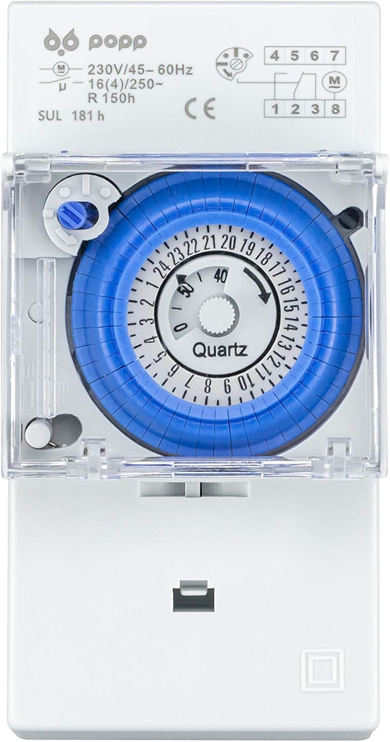
Image: Front view of the timer, showing the analog dial and the wiring terminal diagram.
- Terminals 1 & 2: Power supply for the timer (230V AC, 45-60Hz). Connect the live and neutral wires from your main supply to these terminals.
- Terminals 3, 4, 5: Output contacts for controlling your load.
- Terminal 3: Common contact.
- Terminal 4: Normally Open (NO) contact. The circuit is closed when the timer is ON.
- Terminal 5: Normally Closed (NC) contact. The circuit is open when the timer is ON.
Connect your load (e.g., light, heater) between the common terminal (3) and either the NO (4) or NC (5) terminal, depending on your desired operation. Ensure all connections are tight and secure.
Step 3: Initial Time Setting
After wiring and restoring power, the timer's internal clock will begin to run. To set the current time:
- Rotate the central dial clockwise until the current time aligns with the small arrow indicator on the inner fixed ring. The dial is marked for 24 hours.
- The timer has a 150-hour power reserve, meaning it will keep time for approximately 6 days during a power outage once fully charged.
6. Operating Instructions
The SUL-181H uses small segments around the dial for programming ON/OFF periods.

Image: Angled view of the timer, showing the blue programming dial with individual segments.
Programming ON/OFF Periods:
- Each segment on the blue dial represents a 5-minute interval.
- To set an ON period, push the corresponding segments outwards.
- To set an OFF period, leave the corresponding segments in their inward position.
- The minimum programming duration is 5 minutes (one segment).
- You can set multiple ON/OFF periods throughout the 24-hour cycle.
Manual Override Switch:
The timer includes a manual override switch, typically located near the dial, allowing you to temporarily bypass the programmed settings.
- Automatic Mode (Clock Symbol): The timer operates according to the programmed ON/OFF segments.
- Permanent ON (I Symbol): The output contacts remain continuously ON, regardless of programming.
- Permanent OFF (O Symbol): The output contacts remain continuously OFF, regardless of programming.
Move the switch to the desired position. Remember to return it to the automatic mode for programmed operation.
7. Maintenance
- Cleaning: Disconnect power before cleaning. Use a soft, dry cloth to wipe the timer's exterior. Do not use abrasive cleaners or solvents.
- Inspection: Periodically inspect the wiring connections for tightness and signs of wear or damage.
- Power Reserve: The internal power reserve battery is maintenance-free and recharges automatically when the timer is powered. If the timer is stored for extended periods without power, the reserve may deplete, requiring a few hours of power connection to fully recharge.
8. Troubleshooting
| Problem | Possible Cause | Solution |
|---|---|---|
| Timer does not operate. | No power supply; incorrect wiring; manual override in OFF position. | Check power supply at the breaker. Verify wiring connections. Ensure manual override is in 'Auto' position. |
| Load does not switch ON/OFF as programmed. | Incorrect programming segments; manual override in ON/OFF position; faulty load. | Review programming segments. Check manual override. Test the load independently. |
| Timer loses time during power outage. | Power reserve depleted or not fully charged. | Allow the timer to be connected to power for several hours to fully charge the 150-hour reserve. |
| Timer makes unusual noises. | Internal mechanical issue. | Disconnect power immediately. Contact customer support or a qualified technician. Do not attempt to repair. |
9. Specifications
| Specification | Value |
|---|---|
| Brand | Popp |
| Model | SUL-181H |
| Color | White |
| Material | Plastic |
| Power Supply | 230V AC, 45-60Hz |
| Contact Capacity | 16A (4)/250V |
| Power Reserve | 150 hours |
| Minimum Programming Interval | 5 minutes |
| Number of Program Settings | 5 (This refers to the number of pins/segments for programming) |
| Dial Diameter | 35 mm |
| Item Weight | 120 grams |
| Package Dimensions | 11.5 x 8 x 5.9 cm |
| Certifications | EU Certified |
10. Warranty and Support
For warranty information, please refer to the terms and conditions provided at the point of purchase or contact your retailer. Keep your proof of purchase for any warranty claims.
For technical support or further assistance, please contact Popp customer service through their official website or the contact details provided with your product packaging.