1. Product Overview
The HFBTE Ultrasonic Liquid Flow Meter is a highly reliable and accurate device designed for non-invasive flow measurement of various liquids in pipes. Utilizing transit-time measuring principles, this flowmeter offers a convenient and quick installation process without the need to cut off the flow, ensuring non-destructive installation.
The system comprises a main unit and external clamp-on transducers. This package includes three types of transducers: TS-2, TM-1, and TL-1, accommodating a wide range of pipe diameters.

Figure 1: Complete HFBTE Ultrasonic Liquid Flow Meter system, including the main unit, power cable, signal cables, pipe clamps, and three sets of clamp-on transducers (TS-2, TM-1, TL-1).
2. Setup and Installation
Proper installation is crucial for accurate measurements. The clamp-on design allows for installation without interrupting the flow or cutting the pipe.
2.1 Components Included
- Main Unit: The central processing unit with display and keypad.
- TS-2 Transducer: Small clamp-on transducer (45x25x28mm) for pipe diameters DN25~100mm (0.98 to 3.94 inches).
- TM-1 Transducer: Medium clamp-on transducer (64x39x44mm) for pipe diameters DN50~700mm (1.97 to 27.56 inches).
- TL-1 Transducer: Large clamp-on transducer (97x54x53mm) for pipe diameters DN300~6000mm (11.81 to 236.22 inches).
- Signal Cables, Pipe Clamps, and Power Supply.
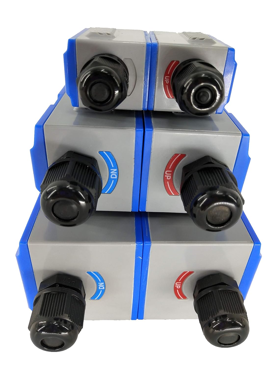
Figure 2: The three types of clamp-on transducers (TS-2, TM-1, TL-1) included with the flow meter, designed for different pipe diameter ranges.
2.2 Choosing the Right Transducer
Select the appropriate transducer pair based on the pipe's outer diameter:
- TS-2: For pipes from DN25 to DN100 (0.98 to 3.94 inches).
- TM-1: For pipes from DN50 to DN700 (1.97 to 27.56 inches).
- TL-1: For pipes from DN300 to DN6000 (11.81 to 236.22 inches).
2.3 Couplant Application
A couplant is essential for effective ultrasonic signal transmission between the transducers and the pipe. Molybdenum Disulfide is recommended. Apply a sufficient amount of couplant to the entire contact surface of the transducers and the pipe wall before clamping them on.
2.4 Mounting the Transducers
- Clean the pipe surface thoroughly at the chosen mounting location to remove any rust, paint, or debris.
- Apply couplant evenly to the transducer faces.
- Position the transducers on the pipe according to the measurement method (Z-method, V-method, etc.) and the calculated distance, ensuring they are firmly clamped. Refer to the main unit's manual for specific spacing calculations.
- Connect the transducer cables to the main unit's designated ports.

Figure 3: Side view of the main unit, showing the secure cable entry points for transducers and power.
2.5 Power Connection
Connect the main unit to a power source. The unit supports DC8~36V or AC85~264V. Ensure the power supply matches the unit's requirements.
3. Operating Instructions
The flow meter operates on the transit-time principle, measuring the time difference of ultrasonic signals traveling with and against the fluid flow.
3.1 Basic Operation
- Power on the main unit. The LCD display will illuminate.
- Use the keypad to navigate through the menu options. The "MENU" button typically accesses the main menu, and arrow keys (▲/▼) are used for navigation. "ENT" confirms selections.
- Input pipe parameters (outer diameter, wall thickness, material) and liquid type into the system. Accurate input of these parameters is critical for precise measurements.
- Verify signal strength and quality. The display usually provides indicators for signal reception. Adjust transducer placement if signals are weak.
- The unit will display real-time flow rate, totalized flow, and other relevant parameters.

Figure 4: The main unit's user interface, featuring an LCD display and a numeric keypad for data entry and menu navigation.
3.2 Measurement Capabilities
- Velocity Range: 0 to ±10 m/s, supporting bi-directional measurement.
- Applicable Liquids: Single liquids capable of transmitting ultrasound, such as water, seawater, sewage, oil, and alcohol.
- Applicable Pipe Materials: Steel, stainless steel, cast iron, copper, PVC, aluminum, glass steel, and other materials. Pipes with liners are also supported.
3.3 Signal Output and Input
- Output:
- 1 way 4-20mA output
- 1 way OCT pulse output
- 1 way Relay output
- Input:
- 3 way 4-20mA input, for connecting PT100 platinum resistors to achieve temperature measurement.
- Interface: RS485, supporting MODBUS protocol for communication with external systems.
4. Maintenance
The HFBTE Ultrasonic Liquid Flow Meter is designed for durability and reliability. Regular maintenance is minimal but important for long-term performance.
4.1 General Care
- Keep the main unit and transducers clean. Wipe them with a soft, dry cloth. Avoid using abrasive cleaners or solvents.
- Ensure all cable connections are secure and free from damage.
- Periodically inspect the transducer mounting for proper alignment and secure clamping. Reapply couplant if necessary.
4.2 Environmental Considerations
- Main Unit: Designed with IP65 protection level, suitable for various industrial environments. Operating temperature range: -20°C to 60°C (-4°F to 140°F). Humidity: ≤85%RH.
- Transducers: Designed with IP68 protection level, allowing for submersion. Operating temperature range: -30°C to 90°C (-22°F to 194°F).
Avoid exposing the unit to extreme temperatures, direct sunlight for prolonged periods, or excessive vibration beyond specified limits.
5. Troubleshooting
This section provides guidance for common issues. For problems not listed here, please contact technical support.
| Problem | Possible Cause | Solution |
|---|---|---|
| No Reading / Erratic Readings |
|
|
| Display Not On |
|
|
| Inaccurate Readings |
|
|
If issues persist after attempting these solutions, please contact HFBTE customer support for further assistance.
6. Technical Specifications
| Parameter | Detail |
|---|---|
| Principle | Transit-time measuring principle |
| Accuracy | ≤1% |
| Repeatability | Better than 0.2% |
| Velocity Range | 0 to ±10 m/s, Bi-directional measurement |
| Applicable Liquids | Single liquid capable of transmitting ultrasound (e.g., water, seawater, sewage, oil, alcohol) |
| Applicable Pipe Materials | Steel, stainless steel, cast iron, copper, PVC, aluminum, glass steel, etc. (Liner allowed) |
| Transducer Types Included | TS-2 (DN25~100mm), TM-1 (DN50~700mm), TL-1 (DN300~6000mm) |
| Transducer Temperature Range | -30°C to 90°C (-22°F to 194°F) |
| Signal Output | 1x 4-20mA, 1x OCT pulse, 1x Relay |
| Signal Input | 3x 4-20mA (for PT100 platinum resistor) |
| Interface | RS485, MODBUS support |
| Power Supply | DC8~36V or AC85~264V |
| Main Unit Protection Level | IP65 |
| Transducer Protection Level | IP68 |
| Main Unit Operating Environment | Temperature: -20°C to 60°C; Humidity: ≤85%RH |
| Product Dimensions (Main Unit) | 7.48 x 2.76 x 7.87 inches |
| Product Weight | 5.51 Pounds |
7. Warranty and Support
For technical assistance, warranty inquiries, or any questions regarding your HFBTE Ultrasonic Liquid Flow Meter, please contact HFBTE customer support.
Manufacturer: HFBTE
For the most up-to-date support information, please visit the official HFBTE store on Amazon or their official website.
Note: Specific warranty terms and conditions may vary. Please refer to your purchase documentation or contact the seller directly for details.


