1. Introduction
The Taidacent 2.4GHz SX1280 Lora Wireless Communication Module is a high-performance wireless transceiver designed for Internet of Things (IoT) applications. It integrates the SEMTECH RF integrated chip SX1280 and the SKYWORKS RF front-end SE2431L. This module utilizes LoRa modulation to achieve extended communication distances and is suitable for various short-range wireless communication scenarios. Its design emphasizes small size, low power consumption, long transmission range, and robust anti-interference capabilities. This module is intended for secondary development by users and does not include a micro-control chip.
2. Key Features
- Working Voltage: 2.0V to 3.7V
- Working Frequency: 2.4GHz to 2.5GHz
- Transmit Power: 22dBm
- Ultra-high Receiving Sensitivity: -134dBm
- Effective Communication Distance: 2km to 4km (visible distance)
- Modulation Methods: Supports LoRa, compatible with FLRC, FSK, and GFSK traditional modulation methods.
- Ranging Engine: Built-in Time-of-Flight (TOF) function for positioning and ranging.
- BLE Compatibility: Compatible with BLE physical layer.
- Communication Interface: SPI, allowing direct connection to various microcontrollers for convenient software programming.
- Antenna Support: Supports dual antenna switching.
3. Applications
- Smart Home systems
- Object tracking and ranging
- Wireless fence solutions
- Wearable sensors, health, and medical devices
- Aircraft remote control systems
4. Setup and Connection
This module is designed for integration into custom circuits. Proper connection to a microcontroller via the SPI interface and power supply is essential for operation. Ensure all connections are secure and follow the pinout diagram carefully.
4.1 Pinout Diagram
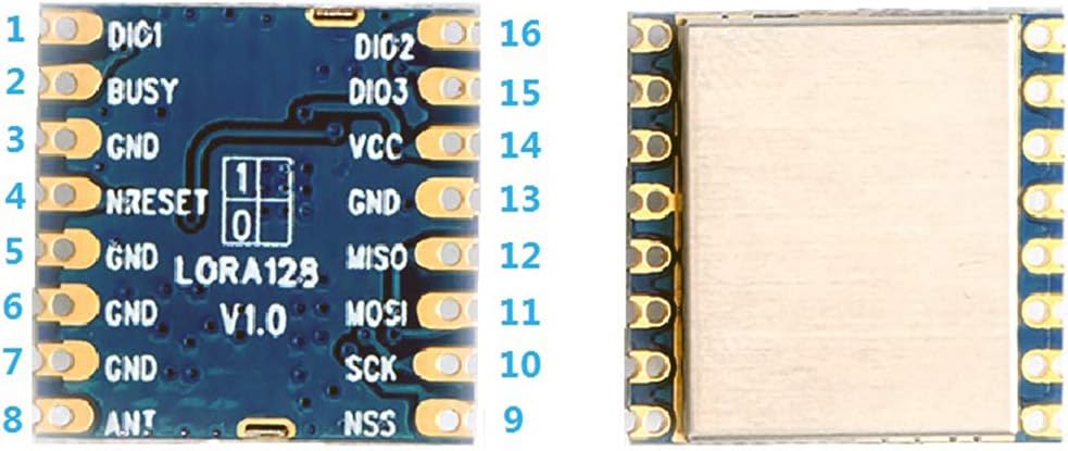
Refer to the pinout diagram (Figure 1) for connecting the module to your development board or microcontroller. Key pins include VCC (power supply), GND (ground), SPI interface pins (MISO, MOSI, SCK, NSS), and digital interrupt pins (DIO1, DIO2, DIO3). The NRESET pin is for module reset, and ANT is for antenna connection.
4.2 Typical Integration

Figure 2 demonstrates a typical integration of the SX1280 module onto a development board, often alongside a display and other peripheral components. This setup facilitates prototyping and testing of wireless communication functionalities. Ensure your development environment provides stable power and correct logic level shifting if necessary.
5. Operating Principles
5.1 LoRa Modulation
LoRa (Long Range) is a spread spectrum modulation technique derived from chirp spread spectrum (CSS) technology. It enables long-range communication with low power consumption, making it ideal for IoT applications. LoRa achieves high sensitivity and robust interference immunity by spreading a narrow-band signal over a wider channel bandwidth.
5.2 Time-of-Flight (TOF) Functionality
The built-in ranging engine supports Time-of-Flight (TOF) functionality. TOF measures the time it takes for a radio signal to travel from the transmitter to the receiver. By accurately measuring this time, the distance between two modules can be calculated, enabling precise positioning and ranging applications.
5.3 SPI Communication Interface
The module communicates with a host microcontroller via the Serial Peripheral Interface (SPI). SPI is a synchronous serial data protocol used for short-distance communication, primarily in embedded systems. It uses four logic signals: SCLK (Serial Clock), MOSI (Master Out Slave In), MISO (Master In Slave Out), and NSS (Slave Select).
6. Specifications
| Parameter | Value |
|---|---|
| Working Voltage | 2.0 ~ 3.7V |
| Working Frequency | 2.4 ~ 2.5GHz |
| Transmit Power | 22dBm |
| Receiving Sensitivity | -134dBm |
| Communication Distance | 2 ~ 4Km (visible distance) |
| Modulation Methods | LoRa, FLRC, FSK, GFSK |
| Interface | SPI |
| Item Weight | 0.16 ounces |
6.1 Dimensions

The module's physical dimensions are approximately 16.00mm x 16.00mm, with a height of 2.10mm. Detailed measurements, including pin spacing and pad sizes, are provided in Figure 3 to assist with PCB layout and integration.
7. Maintenance
To ensure optimal performance and longevity of your Taidacent SX1280 Lora Wireless Communication Module, observe the following maintenance guidelines:
- Environmental Conditions: Operate the module within its specified temperature and humidity ranges. Avoid exposure to extreme temperatures, moisture, or corrosive environments.
- Power Supply: Provide a stable and clean power supply within the specified voltage range (2.0V to 3.7V). Voltage fluctuations or overvoltage can damage the module.
- Physical Handling: Handle the module with care to prevent physical damage to components or solder joints. Avoid static discharge by using appropriate ESD precautions.
- Antenna Connection: Ensure the antenna is securely connected. A loose or incorrect antenna can degrade performance and potentially damage the RF front-end.
- Cleaning: If necessary, clean the module gently with a soft, dry cloth. Avoid using liquids or harsh chemicals.
8. Troubleshooting
If you encounter issues with your Taidacent SX1280 Lora Wireless Communication Module, consider the following troubleshooting steps:
- No Power: Verify that the power supply voltage is within the 2.0V to 3.7V range and that the connections to VCC and GND are correct and secure.
- No Communication (SPI): Check all SPI connections (SCLK, MOSI, MISO, NSS) for continuity and correct pin assignment. Ensure the microcontroller's SPI settings (mode, clock speed) match the module's requirements.
- Poor Range/Signal: Ensure the antenna is properly connected and suitable for the 2.4GHz frequency band. Check for environmental interference or obstructions between modules. Verify transmit power settings in your software.
- Module Not Responding: Try cycling the power to the module or asserting the NRESET pin. Check for any short circuits on the module or development board.
- Software Issues: Review your microcontroller code for correct initialization, configuration, and data handling for the SX1280 chip. Consult the SX1280 datasheet for register configurations.
- Interference: The 2.4GHz band is shared with Wi-Fi, Bluetooth, and other devices. If experiencing interference, consider adjusting channel frequencies or implementing frequency hopping if supported by your application.
9. Warranty and Support
This product is covered by a standard manufacturer's warranty against defects in materials and workmanship. For specific warranty terms, please refer to the documentation provided at the time of purchase or contact Taidacent customer support. Technical support and additional resources, including datasheets and application notes, may be available on the Taidacent official website or through authorized distributors. When seeking support, please provide your product model and a detailed description of the issue.