Hanyoung Nux LC4-P41NA
Hanyoung Nux LC4-P41NA LCD Counter Timer User Manual
Model: LC4-P41NA | Brand: Hanyoung Nux
Introduction
This manual provides detailed instructions for the installation, operation, and maintenance of the Hanyoung Nux LC4-P41NA LCD Counter Timer. This device is designed for precise counting and timing applications, featuring a wide viewing angle LCD with white backlight, expanded prescale range, and Modbus communication capabilities.

Figure 1: Front view of the Hanyoung Nux LC4-P41NA LCD Counter Timer, showing the digital display and control buttons.
Key Features:
- Wide viewing angle LCD with white backlight for clear visibility.
- Expanded prescale setting range (0.00001 to 999999).
- Modbus communication function (RS485) for integration into control systems.
- Offset function for both counter and timer operations.
- Compact dimensions: 48(W) x 48(H) mm.
Part Names and Functions
Refer to the diagram below for an overview of the LC4 series counter timer's parts and their respective functions. The LC4-P41NA model is part of this series.

Figure 2: Diagram illustrating the various parts and their functions for the LC4 series, including the LC4-P41NA model.
- PV display: Displays count value, time value, batch count value, or setting item.
- SV display: Displays counter / timer / batch set value.
- MODE KEY: Enters and quits function mode (auto save function set value during termination). Used to switch the SV display in operation mode (1-stage/2-stage set values/batch set value).
- SHIFT KEY: Enters set value change mode and shifts the set value digits. Enters communication setting mode in function mode.
- DOWN KEY: Reduces set value in function mode and set value change mode.
- UP KEY: Increases set value in function mode and set value change mode.
- RESET KEY: Resets count value, time value, and output status.
- START input indicator: Illuminates when external START signal is applied in timer operation mode.
- INHIBIT input indicator: Illuminates when external INHIBIT signal is applied in timer operation mode.
- RESET input indicator: Illuminates when external RESET signal is applied.
- LOCK set indicator: Illuminates when LOCK is set.
- Communication write inhibit indicator: Illuminates when communication write inhibit is set.
- Timer setting indicator: Illuminates when TIM/TIMB/BTIM operation mode is set, flashes during timing operation.
- BATCH output indicator: Illuminates during BATCH output operation.
- OUT1 output indicator: Illuminates during OUT1 output operation.
- OUT2 output indicator: Illuminates during OUT2 output operation.
- BATCH setting indicator: Illuminates when switching SV display to batch set value.
- SV1 setting indicator: Illuminates when switching SV display to 1-stage set value.
- SV2 setting indicator: Illuminates when switching SV display to 2-stage set value.
Setup and Installation
Model Selection Guide:
The LC4 series offers various configurations. The LC4-P41NA model indicates specific dimensions, display digits, control output, and power voltage. Refer to the table below for a breakdown of the model codes.

Figure 3: Model code breakdown for the LC series, detailing dimensions, settings, display digits, control output, sub output, and power voltage.
| Category | Code | Content |
|---|---|---|
| Model | LC | LCD Counter & Timer |
| Dimensions | 3 | 96(W) × 48(H) mm |
| 4 | 48(W) × 48(H) mm (Applicable to LC4-P41NA) | |
| 6 | 72(W) × 36(H) mm | |
| 7 | 72(W) × 72(H) mm | |
| Settings | P | Preset Counter & Timer (Applicable to LC4-P41NA) |
| Display digits | 4 | 4 digits (9999) ※LC4 only (Applicable to LC4-P41NA) |
| 6 | 6 digits (999999) | |
| Control output | 1 | 1-stage output (Applicable to LC4-P41NA) |
| 2 | 2-stage output | |
| Sub output | N | No sub output (Applicable to LC4-P41NA) |
| C | RS485 (MODBUS-RTU) | |
| Power voltage | A | 100 - 240 V a.c. 50/60 Hz (Applicable to LC4-P41NA) |
Mounting Dimensions:
The LC4-P41NA has dimensions of 48(W) x 48(H) mm (1.89"D x 1.89"W x 1.89"H). Ensure adequate space for installation and ventilation.
Power Connection:
Connect the device to a power supply of 100-240 V a.c. 50/60Hz. Always ensure the power is off before making any connections to prevent electrical shock or damage to the unit.
Operating Instructions
The LC4-P41NA can function as both a counter and a timer. Operation modes and settings are configured using the front panel buttons.
Basic Operation:
- Power On: Once connected to power, the unit will display the current count or time.
- Mode Selection: Press the MODE key to cycle through different operation modes (e.g., counter, timer, batch).
- Setting Values:
- Press the SHIFT key to enter set value change mode. The digit to be changed will flash.
- Use the UP and DOWN keys to adjust the value of the flashing digit.
- Press SHIFT again to move to the next digit.
- Once all digits are set, press MODE to save the setting and exit.
- Resetting: Press the RST key to reset the count value, time value, and output status.
Prescale Setting:
The prescale function allows the input pulses to be scaled to a desired unit. The LC4-P41NA supports a wide prescale range from 0.00001 to 999999. Consult the detailed programming manual (not included here) for specific steps on configuring the prescale value.
Modbus Communication (RS485):
For models equipped with RS485 (Modbus-RTU) communication, the device can be integrated into a larger control system. This allows for remote monitoring and control of the counter/timer functions. Refer to the Modbus communication protocol guide for detailed register maps and communication parameters.
Maintenance
Cleaning:
To maintain optimal performance and readability, periodically clean the unit's display and casing with a soft, dry cloth. Avoid using abrasive cleaners or solvents, as these can damage the plastic and LCD screen.
Environmental Conditions:
Ensure the device operates within the specified ambient temperature and humidity ranges to prevent malfunction and extend its lifespan:
- Ambient Temperature: -10 ~ 55 °C
- Ambient Humidity: 35 ~ 85 % RH (non-condensing)
Avoid installing the unit in locations subject to direct sunlight, excessive dust, corrosive gases, or strong vibrations.
Troubleshooting
If you encounter issues with your LC4-P41NA, review the following common problems and solutions:
- Display is blank:
- Check power connections and ensure the unit is receiving the correct voltage (100-240 V a.c.).
- Verify that the power supply is active.
- Incorrect counting or timing:
- Ensure input signals are within the specified voltage and frequency ranges.
- Check wiring for input signals for proper connection and integrity.
- Verify the prescale setting is configured correctly for your application.
- Confirm the operation mode (counter/timer) is set as intended.
- Output not activating:
- Check the output wiring for correct connections.
- Verify the set value (SV) is correctly configured and the count/time has reached the set point.
- Ensure the output mode is correctly selected.
- Unit not responding to button presses:
- Check if the LOCK indicator is illuminated, indicating the unit is locked. Unlock it if necessary.
- Power cycle the unit (turn off and on) to reset.
For persistent issues, refer to the full technical manual or contact Hanyoung Nux customer support.
Specifications
The following table details the technical specifications for the Hanyoung Nux LC4 series, including the LC4-P41NA model.
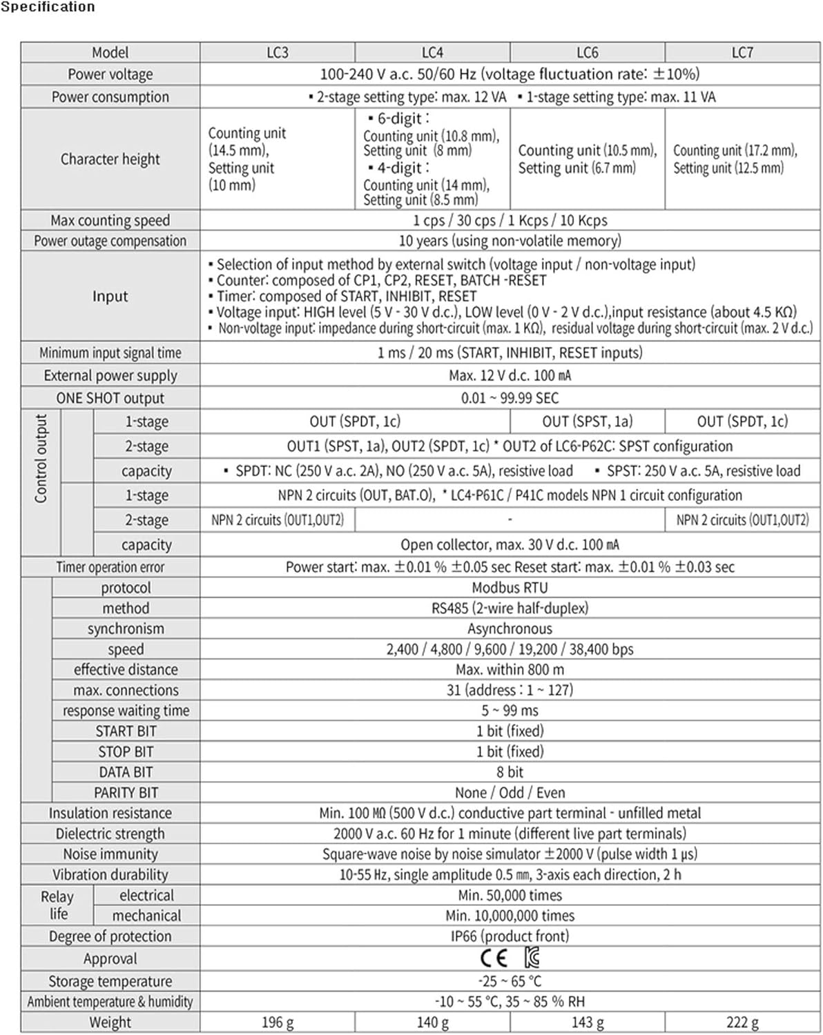
Figure 4: Comprehensive technical specifications for the Hanyoung Nux LC series counter timers.
| Category | Specification |
|---|---|
| Model | LC4-P41NA (48x48mm) |
| Power voltage | 100-240 V a.c. 50/60 Hz (Voltage fluctuation rate: ±10%) |
| Power consumption | 2-stage setting type: max. 12 VA, 1-stage setting type: max. 11 VA |
| Character height | Counting unit (10.8 mm), Setting unit (8 mm) for 4-digit display |
| Max counting speed | 1 cps / 30 cps / 1 Kcps / 10 Kcps |
| Power outage compensation | 10 years (using non-volatile memory) |
| Input | Selection of input method by external switch (voltage input / non-voltage input) Counter: composed of CP1, CP2, RESET, BATCH -RESET Timer: composed of START, INHIBIT, RESET Voltage input: HIGH level (5 V - 30 V d.c.), LOW level (0 V - 2 V d.c.), input resistance (about 4.5 KΩ) Non-voltage input: impedance during short-circuit (max. 1 KΩ), residual voltage during short-circuit (max. 2 V d.c.) |
| Minimum input signal time | 1 ms / 20 ms (START, INHIBIT, RESET inputs) |
| External power supply | Max. 12 V d.c. 100 mA |
| ONE SHOT output | 0.01 - 99.99 sec |
| Control output (1-stage) | OUT (SPDT, 1c) |
| Control output (2-stage) | OUT1 (SPDT, 1a), OUT2 (SPDT, 1c) * OUT2 of LC6-P62C: SPST configuration |
| Control output capacity | SPDT: NC (250 V a.c. 2A), NO (250 V a.c. 5A), resistive load SPST: 250 V a.c. 5A, resistive load |
| NPN 1-stage output | NPN 2 circuits (OUT, BAT.0), * LC4-P61C / P41C models NPN 1 circuit configuration |
| NPN 2-stage output | NPN 2 circuits (OUT1,OUT2) |
| Open collector capacity | Open collector, max. 30 V d.c. 100 mA |
| Timer operation error | Power start: max. ±0.01 % ±0.05 sec Reset start: max. ±0.01 % ±0.03 sec |
| Protocol | Modbus RTU |
| Method | RS485 (2-wire half-duplex) |
| Synchronism | Asynchronous |
| Speed | 2,400 / 4,800 / 9,600 / 19,200 / 38,400 bps |
| Effective distance | Max. within 800 m |
| Max. connections | 31 (address: 1 ~ 127) |
| Response waiting time | 5 ~ 99 ms |
| START BIT | 1 bit (fixed) |
| STOP BIT | 1 bit (fixed) |
| DATA BIT | 8 bit |
| PARITY BIT | None / Odd / Even |
| Insulation resistance | Min. 100 MΩ (500 V d.c.) conductive part terminal - unfilled metal |
| Dielectric strength | 2000 V a.c. 60 Hz for 1 minute (different live part terminals) |
| Noise immunity | Square-wave noise by noise simulator ±2000 V (pulse width 1 μs) |
| Vibration durability | 10-55 Hz, single amplitude 0.5 mm, 3-axis each direction, 2 h |
| Relay life (electrical) | Min. 50,000 times |
| Relay life (mechanical) | Min. 10,000,000 times |
| Degree of protection | IP66 (product front) |
| Approval | CE |
| Storage temperature | -25 ~ 65 °C |
| Ambient temperature & humidity | -10 ~ 55 °C, 35 ~ 85 % RH |
| Weight (LC4) | 140 g |
Warranty and Support
Warranty Information:
Hanyoung Nux products are typically covered by a manufacturer's warranty against defects in materials and workmanship. The specific warranty period and terms may vary by region and distributor. Please retain your proof of purchase for warranty claims.
Customer Support:
For technical assistance, troubleshooting beyond this manual, or warranty service, please contact your local Hanyoung Nux distributor or visit the official Hanyoung Nux website for support resources and contact information.
Ask a question about this manual
Ask about setup, troubleshooting, compatibility, parts, safety, or missing instructions. Manuals+ will review the question and use this page’s manual context to help answer it.