1. Introduction
The Seeku FX3U-48MT is a DIY Programmable Logic Controller (PLC) designed for industrial control applications. This board features a 32-bit high-performance CPU, ensuring fast operation and reliable performance. It supports ladder logic programming using standard software like GX Developer or GX Works2, making it accessible for various automation tasks.
Key features include a DC24V power supply, 24 digital inputs, 24 transistor outputs, and comprehensive analog I/O capabilities. The device also incorporates high-speed input and output channels for demanding applications.

Figure 1: Seeku FX3U-48MT PLC Industrial Control Board with protective casing.
2. Specifications
The following table details the technical specifications of the Seeku FX3U-48MT PLC Industrial Control Board:
| Feature | Description |
|---|---|
| Model Number | FX3U-48MT |
| Power Supply Voltage | DC24V |
| Number of Digital Inputs | 24 |
| Input Type | Digital |
| Number of Outputs | 24 (Transistor) |
| Output Type | Transistor |
| Output Current | 1A |
| Power-off Protection | Supported |
| Analog Input | 3AD 0-10V & 3AD 4-20MA |
| Analog Output | 2DA 0-10V |
| High Speed Input | 6 Channels 3K (or 60K count) |
| High Speed Output | 4 Channels 100K |
| Communication Interfaces | RS232, RS485 |
| Built-in Features | Read time clock, Run/stop switch |
| Floating Point Support | Supported |
| Program Capacity | 8000 Steps EEPROM |
| Programming Language | Ladder Logic |
| Programming Software | GX Developer or GX Works2 |
| Programming Interface | Computer |
| Operating Temperature | 0°F to +131°F (approx. -17.8°C to +55°C) |
| Dimensions (L*W*H) | 180mm * 98mm * 50mm |
| Mounting Hole Dimension | 163mm * 87mm |
| Material | Copper |
| UPC | 634759491545 |
3. Setup and Installation
Follow these steps to properly set up and install your Seeku FX3U-48MT PLC board.
3.1 Physical Installation
- Mounting: The board dimensions are 180mm x 98mm x 50mm. Use the mounting hole dimensions of 163mm x 87mm to secure the PLC in your control panel or enclosure. Ensure adequate ventilation around the unit.
- Terminal Connections: The FX3U-48MT features pluggable terminals for easy and secure wiring. Ensure all connections are firm to prevent intermittent operation.
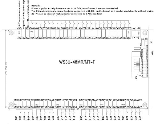
Figure 2: Wiring diagram and physical dimensions of the FX3U-48MT board. Note the remarks regarding DC24V power supply and X0-X5 high-speed input.
3.2 Power Supply Connection
- The PLC requires a DC24V power supply. Connect the positive (+) terminal of the power supply to the +24V DC input and the negative (-) terminal to the GND input on the board.
- Important: Power supply can only be connected to DC 24V. A transformer is not recommended.
- Ensure the power supply is stable and provides sufficient current for the PLC and any connected peripherals.
3.3 Input and Output Wiring
- Digital Inputs (X0-X23): The X input common terminal can be connected with DC- on the board. It can be used directly without additional wiring. Inputs X0-X5 can be configured for high-speed counting or connected to 3 AB encoders.
- Digital Outputs (Y0-Y23): These are transistor outputs with a maximum current of 1A per channel. Connect your loads according to the circuit requirements.
- Analog Inputs (AD): The board provides 3 channels for 0-10V analog input and 3 channels for 4-20mA analog input. Refer to the specific pinout for correct sensor connections.
- Analog Outputs (DA): Two channels are available for 0-10V analog output.

Figure 3: Detailed view of the FX3U-48MT board, highlighting the various input and output terminals and main components.
4. Operating Instructions
This section outlines the procedures for programming and operating the Seeku FX3U-48MT PLC.
4.1 Programming Software
- The PLC is compatible with Mitsubishi GX Developer or GX Works2 software. Install one of these programming environments on your computer.
- The programming language used is Ladder Logic. Familiarity with ladder logic programming is essential for developing control programs.
4.2 Connecting for Programming
- Connect your computer to the PLC using the appropriate RS232 or RS485 communication interface.
- Configure the communication settings in your chosen programming software to match the PLC's default settings or your custom configuration.
4.3 Program Download and Execution
- Develop your ladder logic program in GX Developer or GX Works2.
- Once the program is complete, compile it and download it to the PLC's 8000-step EEPROM memory. The PLC supports high-speed downloading.
- After downloading, use the built-in Run/Stop switch to put the PLC into Run mode to execute your program.
- The PLC supports floating-point operations, allowing for more complex calculations in your programs.
4.4 High-Speed Functions
- High-Speed Inputs: The PLC offers 6 channels for high-speed input, capable of 3K or 60K counts, suitable for encoders or fast pulse signals.
- High-Speed Outputs: Four channels are available for 100K pulse output, ideal for controlling stepper motors or servo drives.

Figure 4: Angled view of the FX3U-48MT board, illustrating the layout of components and connection points.
5. Maintenance
Regular maintenance ensures the longevity and reliable operation of your Seeku FX3U-48MT PLC.
- Environmental Control: Operate the PLC within the specified temperature range of 0°F to +131°F. Avoid exposure to excessive dust, moisture, corrosive gases, or strong electromagnetic interference.
- Cleaning: Periodically clean the exterior of the PLC with a soft, dry cloth. Do not use solvents or abrasive cleaners. Ensure power is disconnected before cleaning.
- Connection Checks: Regularly inspect all wiring connections to ensure they are secure and free from corrosion. Loose connections can lead to intermittent operation or system failures.
- Firmware Updates: Check the manufacturer's website periodically for any available firmware updates that may improve performance or address known issues.
6. Troubleshooting
This section provides solutions to common issues you might encounter with the Seeku FX3U-48MT PLC.
6.1 Power Issues
- PLC does not power on:
- Verify the DC24V power supply is connected correctly and is providing the specified voltage.
- Check the power supply fuse or circuit breaker.
- Ensure the power terminals are securely connected.
6.2 Communication Problems
- Cannot connect to PLC via GX Developer/GX Works2:
- Confirm the correct communication cable (RS232/RS485) is used and properly connected.
- Check the communication port settings (COM port, baud rate, data bits, stop bits, parity) in the software to match the PLC's settings.
- Ensure no other software is using the same communication port.
- Verify the PLC is powered on.
6.3 Program Execution Issues
- Program does not run or outputs are incorrect:
- Ensure the PLC is in Run mode using the built-in switch.
- Verify the program has been successfully downloaded to the PLC.
- Check your ladder logic program for errors or incorrect logic. Use the monitoring features of GX Developer/GX Works2 to debug.
- Inspect input and output wiring for correctness and secure connections.
- Confirm that input sensors are functioning correctly and output devices are receiving power.