1. Product Overview
The Ubiquiti USW-PRO-24-POE is a UniFi Gen 2 10 Gigabit Switch designed to expand and power network infrastructure. It integrates into the Ubiquiti UniFi Enterprise System, offering advanced Layer 3 capabilities and Power over Ethernet (PoE) support for various network devices. This switch provides robust performance and flexible connectivity options for modern network environments.
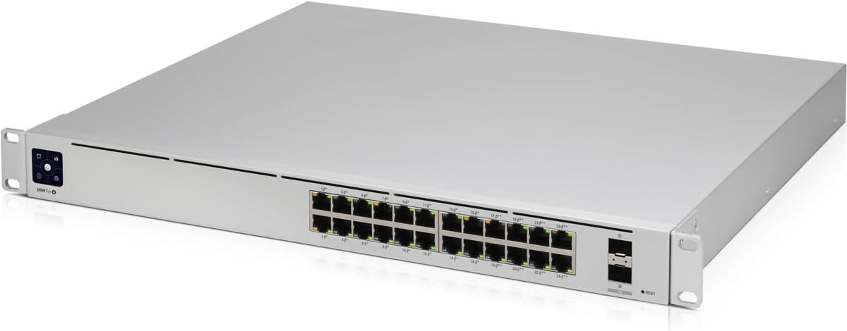
Figure 1: Front view of the Ubiquiti USW-PRO-24-POE switch, showing the 24 RJ45 ports and 2 SFP+ ports.
2. Key Features
- Layer 3 Features: Offers advanced Layer 3 capabilities including inter-VLAN routing, static routing, and DHCP server functionality.
- Near-Silent Cooling: Integrated fans with built-in PWM (Power Management) control, air ducts, covers, and temperature sensors ensure quiet operation.
- Fiber Connectivity: Two SFP+ ports enable high-capacity uplinks of up to 10 Gbps for connecting to high-performance storage servers or other switches.
- 802.3bt PoE++: Eight ports provide 802.3bt PoE++ with up to 64W of power per port. The remaining 16 ports offer 802.3af/at PoE.
- Redundant Power Option: Supports an external DC input interface (USP RPS interface) for power redundancy, providing backup in case of internal PSU failure.
3. Package Contents
Verify that the following items are included in your package:
- Ubiquiti USW-PRO-24-POE Switch
- Power Cord
- Rackmount Ears (2)
- Rackmount Screws (4)
4. Hardware Overview
4.1 Front Panel

Figure 2: Detailed front view of the Ubiquiti USW-PRO-24-POE switch, highlighting the port layout and status indicators.
The front panel of the USW-PRO-24-POE features the following components:
- RJ45 Ports (1-24): 24 Gigabit Ethernet ports. Ports 1-16 support 802.3af/at PoE, and ports 17-24 support 802.3bt PoE++.
- SFP+ Ports (25-26): Two 10 Gigabit Ethernet SFP+ ports for high-speed fiber uplinks.
- Reset Button: Used to reset the device to factory defaults.
- Status Display: An integrated display provides real-time status information.
4.2 Rear Panel
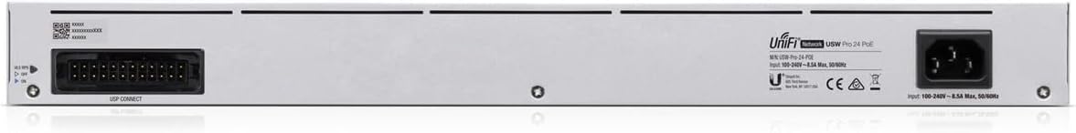
Figure 3: Rear view of the Ubiquiti USW-PRO-24-POE switch, showing the AC power inlet and USP RPS connector.
The rear panel includes:
- AC Power Inlet: Connects the included power cord for primary power (100-240VAC).
- USP RPS Connector: An interface for connecting a Ubiquiti UniFi SmartPower RPS for redundant power supply.
4.3 Side Panel

Figure 4: Side view of the Ubiquiti USW-PRO-24-POE switch, illustrating its rack-mountable design.
The side panels feature mounting points for attaching the included rackmount ears.
5. Installation and Setup
5.1 Mounting the Switch
- Attach the two rackmount ears to the sides of the switch using the provided screws.
- Secure the switch into a standard 1U rack space using appropriate rack screws (not included). Ensure adequate ventilation around the device.
5.2 Connecting Power
- Connect the included power cord to the AC Power Inlet on the rear panel of the switch.
- Plug the other end of the power cord into a suitable power outlet.
- For redundant power, connect a Ubiquiti UniFi SmartPower RPS unit (sold separately) to the USP RPS Connector on the rear panel.
5.3 Network Connection
- Connect your network devices (e.g., computers, access points, IP cameras) to the RJ45 Ethernet ports on the front panel using standard Ethernet cables.
- For high-speed uplinks, insert compatible SFP+ modules (sold separately) into the SFP+ ports and connect them using appropriate fiber optic cables.
5.4 UniFi Controller Integration
The USW-PRO-24-POE switch is managed by the UniFi Network Controller. This requires a UniFi Cloud Key, UniFi Dream Machine, or a self-hosted UniFi Network application.
- Ensure your UniFi Network Controller is running and accessible on your network.
- The switch should appear in the UniFi Network Controller's device list for adoption. Follow the on-screen instructions to adopt the device.
- Note: If the switch ships with older firmware, it may require a manual firmware update before it can be successfully adopted by the controller. Refer to Ubiquiti's support documentation for manual firmware update procedures.
6. Operation
6.1 Basic Operation
Once powered on and adopted by the UniFi Network Controller, the USW-PRO-24-POE switch will automatically provide network connectivity and Power over Ethernet (PoE) to connected devices as configured. All management and monitoring are performed through the UniFi Network Controller interface.
6.2 LED Indicators
The switch features various LED indicators to provide status information:
- System LED: Indicates the device's operational status (e.g., white for ready for adoption, blue for adopted).
- RJ45 Port LEDs: Indicate link/activity and PoE status for each connected device.
- SFP+ Port LEDs: Indicate link/activity for the fiber uplink connections.
6.3 Layer 3 Features Configuration
Advanced Layer 3 features such as inter-VLAN routing, static routing, and DHCP server functionality can be configured via the UniFi Network Controller. Consult the UniFi Network Controller documentation for detailed instructions on configuring these features.
7. Maintenance
7.1 Firmware Updates
Regularly check for and apply firmware updates through the UniFi Network Controller. Firmware updates provide performance improvements, security enhancements, and bug fixes. Ensure a stable power supply during the update process.
7.2 Cleaning
To maintain optimal performance, ensure that the ventilation openings are clear of dust and debris. Use a soft, dry cloth to clean the exterior of the switch. Do not use liquid cleaners or aerosols.
7.3 Cooling System
The integrated cooling system is designed for near-silent operation. Ensure that the switch is installed in an environment with adequate airflow and within its specified operating temperature range to prevent overheating.
8. Troubleshooting
- No Power: Verify that the power cord is securely connected to both the switch and a functional power outlet. If using redundant power, check the status of the USP RPS unit.
- No Network Connectivity: Ensure all Ethernet and fiber cables are properly connected. Check the UniFi Network Controller to confirm the switch is adopted and configured correctly. Verify VLAN settings if applicable.
- PoE Not Working: Confirm that the connected device is PoE compatible. Check the PoE settings for the specific port in the UniFi Network Controller. Ensure the total power budget of the switch is not exceeded.
- Adoption Failure: Ensure the UniFi Network Controller is running and reachable by the switch. If the switch has older firmware, a manual firmware update may be required before it can be adopted.
- High Fan Noise: While designed for quiet operation, persistent high fan noise may indicate high device load or obstructed airflow. Check the ambient temperature and ensure ventilation openings are clear.
9. Technical Specifications
| Attribute | Value |
|---|---|
| Model | USW-PRO-24-POE |
| Dimensions (L x W x H) | 19.69" x 11.81" x 1.77" (500 x 300 x 45 mm) |
| Weight | 3.8 kg (8.36 lbs) |
| Power Input | 100-240VAC, 50/60 Hz |
| Total Network Ports | 24 x RJ45 Gigabit Ethernet, 2 x SFP+ 10 Gigabit Ethernet |
| PoE Standards | 802.3af/at (Ports 1-16), 802.3bt PoE++ (Ports 17-24) |
| Max. PoE Wattage per Port (802.3bt) | 64W |
| Total PoE Power Availability | 400W |
| Redundant Power | USP RPS DC Input |
| Manufacturer | Ubiquiti Networks |
| UPC | 817882028349 |
10. Warranty Information and Support
This Ubiquiti Networks product is covered by a limited warranty. For detailed warranty terms, technical support, and additional resources, please visit the official Ubiquiti Networks support website. You can find documentation, firmware downloads, and community forums to assist with any questions or issues you may encounter.
Official Support Website: www.ui.com/support