1. Introduction
This manual provides essential information for the safe and effective operation, setup, and maintenance of your Biltek 50Amp Non-Pilot Arc Plasma Cutter. Please read this manual thoroughly before using the equipment to ensure proper function and to prevent injury or damage.
2. Safety Information
WARNING: Plasma cutting involves high voltage, intense light, heat, and fumes. Failure to follow safety precautions can result in serious injury or death.
- Electrical Safety: Ensure the unit is properly grounded. Do not operate in wet conditions. Always disconnect power before performing maintenance or changing consumables.
- Eye and Face Protection: Always wear a welding helmet with appropriate shade settings to protect against arc flash. Wear safety glasses under the helmet.
- Body Protection: Wear flame-resistant clothing, gloves, and closed-toe shoes to protect against sparks and molten metal.
- Fume Ventilation: Operate in a well-ventilated area to avoid inhaling hazardous fumes. Use local exhaust ventilation if necessary.
- Fire Prevention: Keep flammable materials away from the cutting area. Have a fire extinguisher readily available.
- Hot Materials: Cut materials will be extremely hot. Allow them to cool before handling.
- Air Supply: Ensure your air compressor provides clean, dry, oil-free air.
3. Package Contents
Verify that all items listed below are included in your package. If any items are missing or damaged, contact customer support.
- 1x Plasma Cutter Power Supply
- 1x Cutting Torch
- 1x 30A 250V NEMA L6-30P Plug (for 220V connection)
- 6x Replacement Consumables (2x Nozzle Tips, 2x Electrodes, 1x Ceramic Cup, 1x Ceramic Ring)
- 1x Ground Clamp
- 1x Air Filter/Regulator
- 1x Air Hose
- 4x Hose Clamps
- 2x Air Connectors
- 1x User Manual

4. Product Overview
Familiarize yourself with the main components and controls of your plasma cutter.
4.1 Front Panel

- ON/OFF Switch: Main power control.
- Current Adjustment Knob: Used to set the output amperage (10-50A).
- O.C. Indicator: Over-current warning light.
- Torch Connection Port: For connecting the cutting torch.
- Ground Clamp Connection Port: For connecting the ground clamp.
4.2 Rear Panel
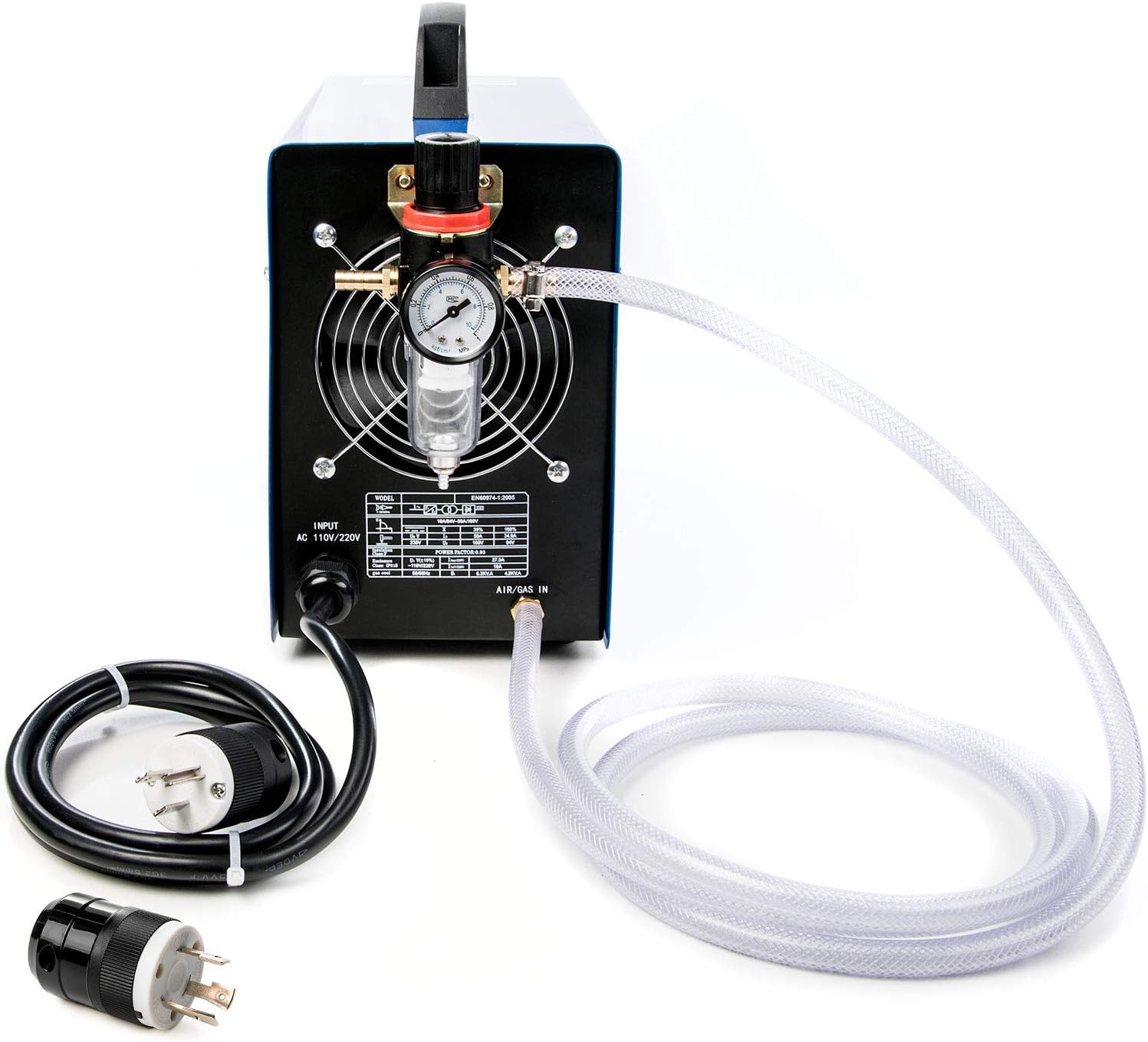
- Power Input Cable: Pre-attached 110V US plug.
- Air Inlet: Connection point for the air supply hose and filter/regulator.
- Cooling Fan: Ensures proper ventilation during operation.
5. Setup
Follow these steps to set up your plasma cutter before operation.
5.1 Power Connection
The unit comes with a pre-attached 110V US plug. For optimal 50A cutting performance, a 220V connection is required. The package includes a 30A 250V NEMA L6-30P plug for this purpose.
- 110V Connection: Plug the pre-attached 110V plug into a suitable 110V outlet. Note that maximum cutting capacity may be reduced.
- 220V Connection: If you intend to use 220V, you will need to replace the 110V plug with the provided L6-30P plug. This procedure should be performed by a qualified electrician to ensure safety and compliance with local electrical codes.

5.2 Air Supply Connection
A clean, dry, oil-free air supply from an air compressor is essential for plasma cutting. The required air flow rate is 0.6-0.75Mpa (3.0 scfm @ 70PSI).
- Attach the air filter/regulator to the air inlet on the rear of the plasma cutter.
- Connect one end of the air hose to the air filter/regulator using a hose clamp.
- Connect the other end of the air hose to your air compressor's output using an air connector and hose clamp.
- Ensure all connections are secure to prevent air leaks.
5.3 Torch and Ground Clamp Connection
- Connect the cutting torch cable to the designated torch connection port on the front panel. Ensure it is fully inserted and secured.
- Connect the ground clamp cable to the designated ground clamp connection port on the front panel.

6. Operating Instructions
Before operating, ensure all safety precautions are understood and followed.
6.1 Preparation
- Wear all necessary personal protective equipment (PPE), including a welding helmet, safety glasses, gloves, and flame-resistant clothing.
- Ensure the workpiece is clean, dry, and free of rust, paint, or other coatings that could interfere with the cut or produce excessive fumes.
- Securely attach the ground clamp to the workpiece or the work table as close to the cutting area as possible.
- Ensure adequate ventilation in the work area.
6.2 Basic Operation
- Turn on the air compressor and adjust the air pressure to the recommended setting (0.6-0.75Mpa).
- Turn on the plasma cutter using the ON/OFF switch on the front panel.
- Adjust the cutting current using the adjustment knob according to the material thickness and type. Start with lower settings and increase as needed.
- Position the torch nozzle close to the starting point of the cut on the workpiece.
- Press the trigger on the cutting torch to initiate the arc. The non-pilot arc requires the torch tip to touch the workpiece to start the arc.
- Once the arc is established and penetrates the material, move the torch steadily along the desired cut line. Maintain a consistent speed and distance from the workpiece for a clean cut.
- Release the trigger to stop the arc.
6.3 Cutting Tips
- Material Thickness: Adjust amperage based on material thickness. Thicker materials require higher amperage.
- Cutting Speed: Too slow can cause excessive dross and a wide kerf. Too fast can result in an incomplete cut.
- Torch Angle: Maintain a slight angle (5-15 degrees) for optimal cutting.
- Consumables: Regularly inspect and replace worn consumables (nozzle, electrode, ceramic cup, ceramic ring) for best cutting performance.
7. Maintenance
Regular maintenance ensures the longevity and optimal performance of your plasma cutter.
7.1 General Cleaning
- Keep the unit clean and free of dust and debris. Use compressed air to blow out internal components periodically, ensuring the unit is unplugged.
- Clean the exterior with a dry cloth. Do not use solvents.
7.2 Consumable Replacement
The torch consumables (nozzle tips, electrodes, ceramic cup, ceramic ring) wear out over time and must be replaced to maintain cut quality.
- Ensure the plasma cutter is turned off and unplugged.
- Unscrew the ceramic cup from the torch head.
- Remove the old nozzle tip and electrode.
- Insert new electrode and nozzle tip.
- Replace the ceramic ring and screw the ceramic cup back onto the torch head, ensuring it is finger-tight.

7.3 Air Filter Maintenance
Periodically check the air filter/regulator for accumulated moisture or debris. Drain any collected water and clean or replace the filter element as needed to ensure a clean air supply.
8. Troubleshooting
This section addresses common issues you might encounter with your plasma cutter.
| Problem | Possible Cause | Solution |
|---|---|---|
| No arc when trigger is pressed |
|
|
| Poor cut quality (rough, excessive dross) |
|
|
| O.C. (Over-Current) light illuminates |
|
|
9. Specifications
Key technical specifications for the Biltek 50Amp Plasma Cutter.
| Feature | Specification |
|---|---|
| Model | BIL50+P220V |
| Input Voltage | 110-220V, 1-PH, 50/60Hz (Dual Voltage) |
| Input Current | 20-40A |
| Output Current | 15-50A |
| Optimal Cut Thickness | 8mm (approx. 5/16 inch) |
| Maximum Cut Thickness | 10mm (approx. 3/8 inch) |
| Severance Cut Thickness | 12mm (approx. 1/2 inch) |
| Required Air Flow Rate | 0.6-0.75Mpa (3.0 scfm @ 70PSI) |
| Duty Cycle | 35% @ 40°C (104°F) |
| Materials Cut | Stainless steel, alloy steel, mild steel, sheet metal, copper, aluminum, etc. |
10. Warranty and Support
For warranty information, please refer to the documentation provided at the time of purchase or contact your retailer. For technical support or inquiries regarding your Biltek Plasma Cutter, please contact the manufacturer or authorized service center.