1. Introduction
This manual provides comprehensive instructions for the safe and effective operation of your Godox DP400III Studio Flash Light. Please read this manual thoroughly before use to ensure proper functionality and to prevent damage to the unit or injury to yourself or others. Keep this manual for future reference.
2. Product Overview
The Godox DP400III is a 400Ws studio flash light featuring a built-in Godox 2.4G wireless X system, Bowens mount, and stable 5600K color temperature. It is designed for various photography applications requiring powerful and consistent lighting.
2.1 Key Features
- 400Ws Flash Output: Provides ample power for studio photography.
- Built-in Godox 2.4G Wireless X System: Enables wireless control with compatible triggers (sold separately).
- Bowens Mount: Compatible with a wide range of light shaping accessories.
- Stable Color Temperature: 5600K ± 200K for consistent lighting.
- Fast Recycle Time: Quick recycling for continuous shooting.
- Adjustable Modeling Lamp: 150W modeling lamp with adjustable brightness.
- Wireless ID Function: Offers strong anti-interference ability with 01-99 IDs.
2.2 Components

Figure 1: The Godox DP400III Studio Flash Light, shown with its power cable and a protective cap. This image displays the main unit, including the flash tube and modeling lamp, ready for assembly.

Figure 2: Detailed views of the DP400III. Top left shows the versatile Bowens mount for attaching accessories. Top right displays the wireless control port and main dial. Bottom left highlights the durable handle for easy positioning. Bottom right shows the concise and clear LCD panel for settings adjustment.
3. Setup
- Mounting: Attach the flash unit to a light stand using the integrated mounting bracket. Secure it firmly by tightening the locking knob.
- Adjusting Angle: The unit features a stepless adjustable angle and a fixed handle. Loosen the angle adjustment knob, position the flash as desired, and then tighten the knob to secure the angle.
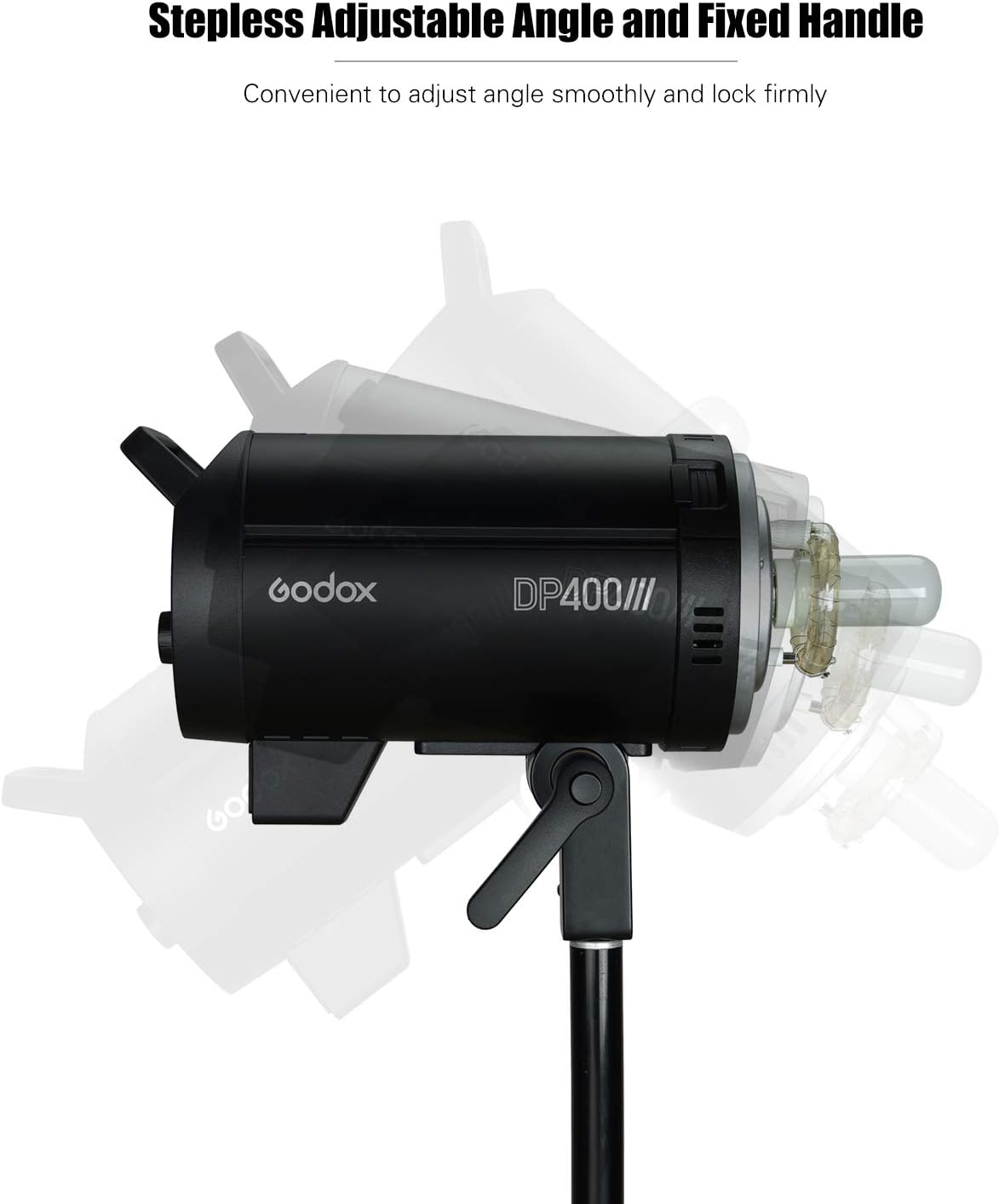
Figure 3: The DP400III mounted on a light stand, illustrating the stepless adjustable angle mechanism and the fixed handle for convenient positioning.
- Power Connection: Connect the power cable to the flash unit and then to a suitable power outlet. Ensure the voltage matches the unit's requirements (100-120V/50-60Hz or 200-240V/50-60Hz).
- Accessory Attachment: If using light shaping accessories (e.g., softbox, reflector), attach them to the Bowens mount on the front of the flash unit. Ensure they are securely locked in place.
4. Operating Instructions
4.1 Power On/Off
Press the power button located on the control panel to turn the unit on or off. The LCD panel will illuminate upon power-on.
4.2 Flash Output Adjustment
Rotate the main dial on the control panel to adjust the flash output. The output can be set from 1/64 to 1/1 in 61 steps. The current setting will be displayed on the LCD panel.
4.3 Modeling Lamp Operation
The 150W modeling lamp has three modes: OFF, PROP (Proportional), and Percentage. In PROP mode, the modeling lamp's brightness changes proportionally with the flash output. In Percentage mode, the brightness is adjustable from 5% to 100% independently. Use the dedicated modeling lamp button to cycle through modes and adjust brightness.
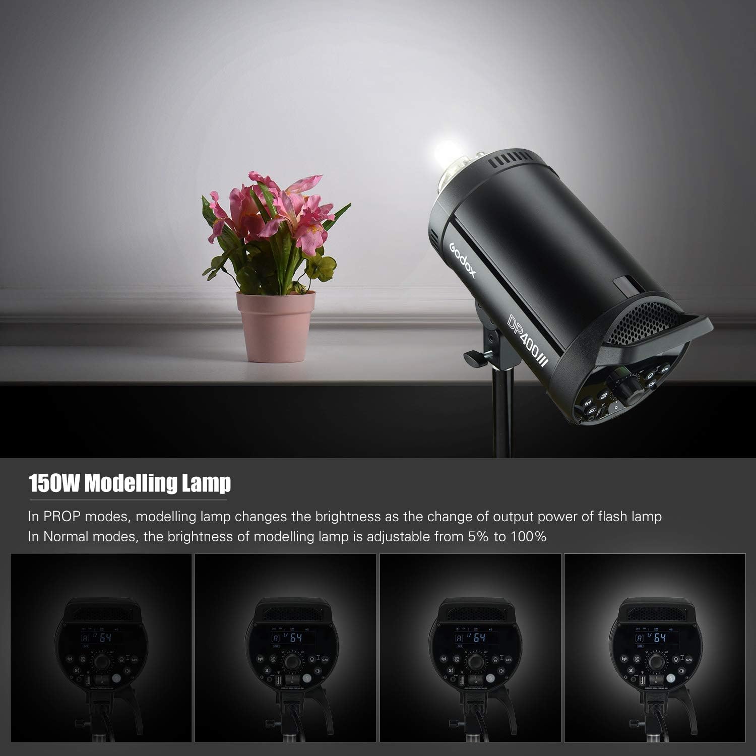
Figure 4: Illustration of the 150W modeling lamp functionality. The top image shows the lamp in use. The bottom row demonstrates different brightness levels of the modeling lamp, adjustable from 5% to 100% in Normal mode, or proportionally in PROP mode.
4.4 Godox 2.4G Wireless X System
The DP400III features a built-in 2.4G wireless X system for remote control. To activate, press the dedicated wireless button. This system allows for:
- Group Control: Set up to 16 flash groups (0-9, A-F).
- Channel Selection: Choose from 32 channels (1-32) to avoid interference.
- Wireless ID: Utilize the newly added wireless ID (01-99) for enhanced anti-interference capabilities.
- Remote Adjustment: Adjust flash power, control the modeling lamp, and manage other settings using compatible Godox 2.4G wireless triggers (e.g., X2, XPro, XT16, FT-16, sold separately).
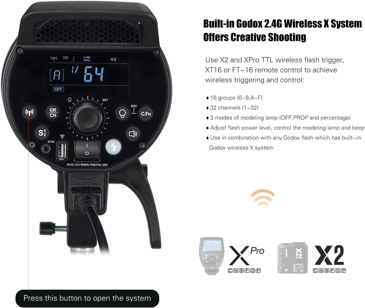
Figure 5: The control panel of the DP400III, illustrating the buttons and display for configuring the built-in Godox 2.4G Wireless X System. Compatible wireless triggers like the XPro and X2 are shown for reference.
4.5 Triggering Methods
- Sync Cord: Connect a sync cord to the flash unit's sync port.
- Test Button: Press the test button on the unit for a manual flash.
- Slave Triggering: The unit can be triggered by another flash.
- Wireless Control Port: Use a compatible Godox wireless trigger.
5. Maintenance
- Cleaning: Use a soft, dry cloth to clean the exterior of the flash unit. Do not use abrasive cleaners or solvents.
- Flash Tube Replacement: The flash tube is a consumable item. If it fails or its performance degrades, it can be replaced by a qualified technician.
- Storage: Store the unit in a cool, dry place away from direct sunlight and excessive humidity.
- Handling: Avoid dropping or subjecting the unit to strong impacts.
6. Troubleshooting
| Problem | Possible Cause | Solution |
|---|---|---|
| Flash does not fire. | Not powered on; sync cord loose; trigger not paired; flash output too low. | Ensure power is on; check sync cord connection; pair wireless trigger; increase flash output. |
| Long recycle time. | High flash output setting; unit overheating. | Reduce flash output; allow unit to cool down. |
| Inconsistent flash output. | Unstable power supply; flash tube nearing end of life. | Ensure stable power; consider flash tube replacement. |
| Wireless control not working. | Incorrect group/channel/ID settings; trigger out of range; trigger battery low. | Verify group, channel, and ID settings; move trigger closer; replace trigger battery. |
7. Specifications
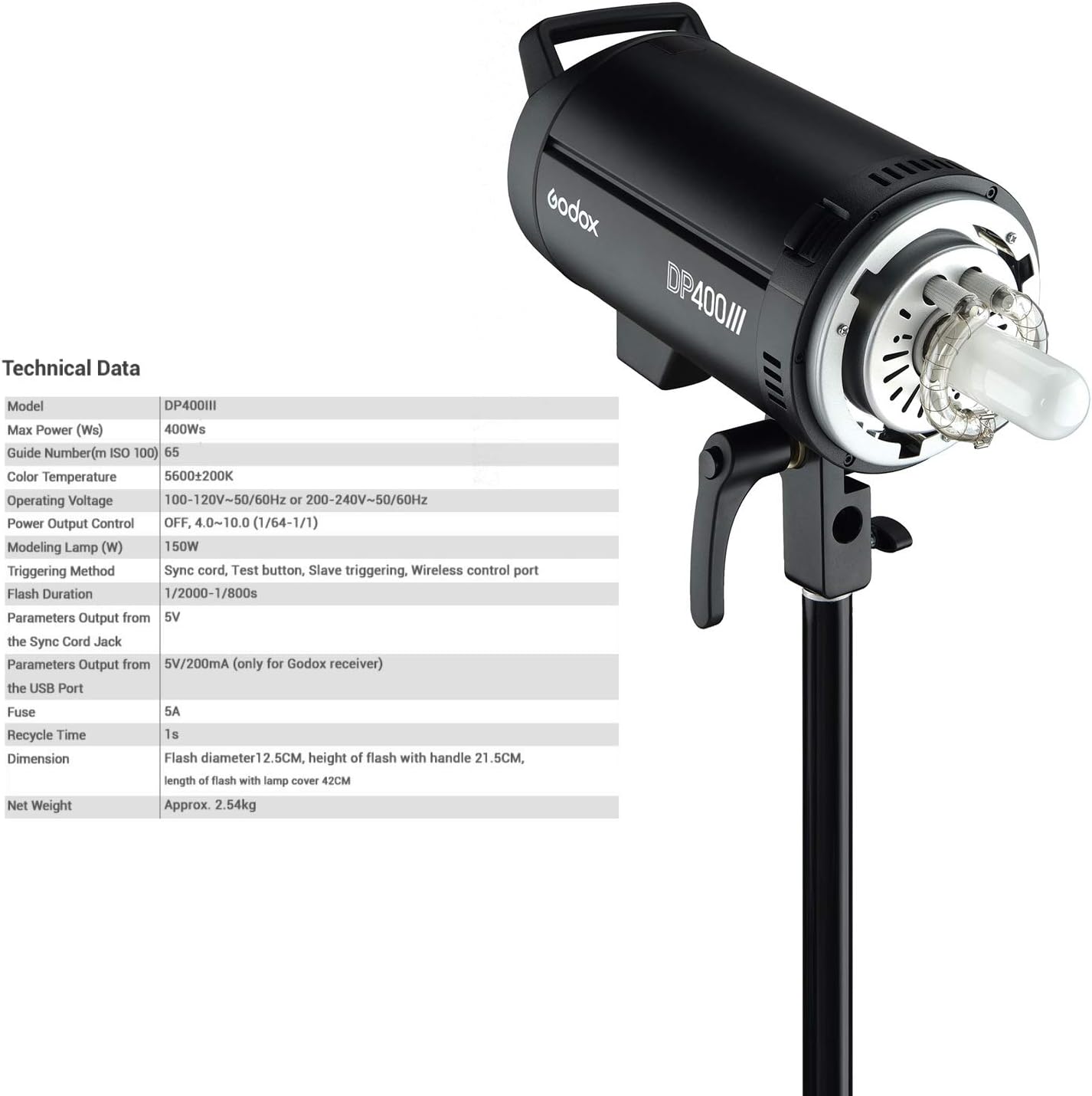
Figure 6: A detailed table outlining the technical specifications of the Godox DP400III Studio Flash Light.
| Specification | Value |
|---|---|
| Model | DP400III |
| Max Power (Ws) | 400Ws |
| Guide Number (m ISO 100) | 65 |
| Color Temperature | 5600±200K |
| Operating Voltage | 100-120V~50/60Hz or 200-240V~50/60Hz |
| Power Output Control | OFF, 4.0-10.0 (1/64-1/1) |
| Modeling Lamp | 150W |
| Triggering Method | Sync cord, Test button, Slave triggering, Wireless control port |
| Flash Duration | 1/2000-1/800s |
| Parameters Output from the Sync Cord Jack | 5V |
| Parameters Output from the USB Port | 5V/200mA (only for Godox receiver) |
| Fuse | 5A |
| Recycle Time | 1s |
| Dimension | Flash diameter 12.5cm, height of flash with handle 21.5cm, length of flash with lamp cover 42cm |
| Net Weight | Approx. 2.54kg |
8. Warranty and Support
For warranty information, please refer to the documentation provided with your purchase or visit the official Godox website. If you encounter any issues or require technical assistance, please contact Godox customer support or your authorized dealer.
You can find more information and support resources on the GODOX Store on Amazon.