Introduction
This Walfront AC Contactor features a unique 4-position switch, supporting both manual control and automatic operation. It offers optimized space and improved performance, with a 70% volume reduction compared to traditional contactors. Designed for energy efficiency, it reduces power consumption by 75% compared to traditional models. The unit operates quietly, with noise levels below 15 dB, ensuring safe and silent use. A reliable electromagnetic system provides fast response and switching. Its excellent electrical conductivity and unique gas jet arc extinguishing structure enhance electrical safety.
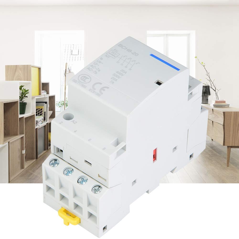
Figure 1: Front view of the Walfront AC Contactor.
Setup and Installation
Proper installation is crucial for the safe and efficient operation of the AC contactor. Ensure all power sources are disconnected before beginning installation.
- Mounting: The contactor is designed for DIN rail mounting. Securely attach the contactor to a standard 35mm DIN rail within an electrical enclosure.
- Wiring: Connect the main power lines to the appropriate terminals (L1, L2, L3, N for 4-pole, or L1, L2 for 2-pole configurations). Connect the load lines to the corresponding output terminals. Ensure all connections are tight and secure.
- Control Circuit: Connect the control circuit wiring to the A1 and A2 terminals for coil activation. Refer to your specific control scheme for detailed connections.
- Terminal Connections: Use appropriate tools for terminal connections. A screwdriver is recommended for tightening terminal screws. Avoid using power drills, which can overtighten and damage terminals.

Figure 2: Example installation of the AC Contactor within an electrical panel.

Figure 3: Use a screwdriver for terminal connections to prevent damage.
After all connections are made, double-check wiring against your electrical diagram before restoring power.
Operating Instructions
The Walfront AC Contactor features a versatile 4-position control switch for flexible operation modes.

Figure 4: The 4-position control switch for manual and automatic operation.
- Auto Operation: In this mode, the contactor responds to signals from the control circuit (e.g., thermostat, timer, PLC). The contactor will switch on or off automatically based on the control input.
- Manual Switching On: This position allows for manual activation of the contactor, overriding the automatic control. The contactor will remain ON until manually switched off or to another mode.
- Manual Forced Switching Off: This position forces the contactor OFF, overriding automatic control. The contactor will remain OFF until manually switched on or to another mode.
- Manual Permanent Switching On: Similar to "Manual Switching On" but designed for continuous manual operation. Consult your specific model's documentation for any subtle differences between "Manual Switching On" and "Manual Permanent Switching On."
Always ensure the desired operating mode is selected carefully to prevent unintended equipment operation.
Maintenance
Regular maintenance helps ensure the longevity and reliable performance of your AC contactor. Always disconnect power before performing any maintenance.
- Visual Inspection: Periodically inspect the contactor for any signs of physical damage, discoloration, or loose connections. Check for dust or debris accumulation.
- Cleaning: Use a dry, soft cloth or a small brush to gently remove dust and dirt from the contactor's exterior. Do not use liquids or abrasive cleaners.
- Terminal Tightness: Over time, terminal screws can loosen due to vibration or thermal cycling. Periodically check and retighten all terminal connections to the recommended torque.
- Contact Inspection: If accessible and safe to do so, inspect the main contacts for excessive wear or pitting. This typically requires professional assessment.
If any issues are detected during maintenance, consult a qualified electrician or contact support.
Troubleshooting
This section provides solutions to common issues you might encounter with your AC contactor.
| Problem | Possible Cause | Solution |
|---|---|---|
| Contactor does not switch ON/OFF | No control signal; Incorrect wiring; Coil failure; Manual switch in wrong position. | Check control circuit power and signal; Verify wiring connections; Test coil continuity; Ensure manual switch is in 'Auto' or correct manual position. |
| Contactor hums loudly | Loose connections; Contaminated pole faces; Incorrect voltage. | Tighten mounting screws and terminal connections; Clean pole faces (power off); Verify supply voltage matches contactor rating. |
| Overheating | Overload condition; Poor ventilation; Loose connections; Incorrect contactor sizing. | Check load current; Ensure adequate airflow around contactor; Tighten all connections; Verify contactor rating is suitable for the application. |
| Contacts welded shut | Excessive current; Short circuit; Frequent switching under heavy load. | Replace contactor; Investigate and correct overload/short circuit condition; Consider a higher-rated contactor or different switching strategy. |
For issues not listed or if solutions do not resolve the problem, contact a qualified technician.
Technical Specifications
Below are the key technical specifications for the Walfront AC Contactor.
| Feature | Value |
|---|---|
| Rated Voltage (Ue) | 400 VAC |
| Frequency | 50Hz |
| Electrical Life | 100,000 cycles |
| Max. Switching Operations | 100 times/day |
| Insulation Voltage (Ui) | 500 VAC |
| Pollution Level | 2 |
| Rated Impulse Withstand Voltage (Uimp) | 2.5 kV (4 kV at 12/24/48VAC) |
| Protection Rating (IEC 60529) | IP20 (IP40 after installation in distributor) |
| Operating Temperature | -5°C to +60°C |
| Storage Temperature | -40°C to +70°C |
| Humidity and Heat Resistance (IEC60068.1) | Category 2 (95% RH at 55°C) |
| Contact Options | 4NO, 2NO 2NC (This model is 2NO 2NC) |
| Current Rating | 25 A |
| Operating Mode | ON-OFF-ON |
| Connector Type | DIN Rail Connector |
| Switch Type | Mechanical and Electromechanical |
| Terminal Type | Blade |
| Material | Plastic |
| Circuit Type | 4-way or 2-way |
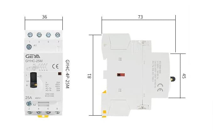
Figure 5: Dimensions of the Walfront AC Contactor.

Figure 6: Note on potential variations between new and old models. Functionality remains consistent.
Warranty Information
Specific warranty details for this product are not provided in the available information. Please refer to the retailer's return policy or contact the seller directly for warranty terms and conditions. Generally, electrical components come with a limited manufacturer's warranty against defects in materials and workmanship.
Customer Support
For technical assistance, troubleshooting beyond this manual, or inquiries regarding your Walfront AC Contactor, please contact your point of purchase or the Walfront customer service department. You may find contact information on the product packaging or the retailer's website.
For more information about Walfront products, visit the official Walfront Brand Store.