1. Introduction
This instruction manual provides comprehensive guidance for the installation, operation, and maintenance of your Shaved Door Handle Popper Kit. This universal kit is designed to provide remote keyless entry and release functionality for two front doors, with additional channels for a third door, fourth door, hatch, or trunk. Please read this manual thoroughly before beginning installation or operation to ensure proper function and safety.
2. Safety Information
- Professional Installation Recommended: Due to the complexity of automotive electrical systems and the need for custom fabrication for shaved door handles, professional installation by a qualified technician is highly recommended.
- Disconnect Battery: Always disconnect the vehicle's negative battery terminal before performing any electrical work to prevent short circuits and electrical hazards.
- Proper Wiring: Ensure all wiring connections are secure, insulated, and routed away from moving parts, sharp edges, and heat sources. Use appropriate gauge wire and fuses.
- Test Functionality: Before fully reassembling the vehicle, thoroughly test all functions of the kit to ensure correct operation and safety.
- Vehicle Compatibility: This is a universal kit. Ensure it is suitable for your specific vehicle application and that there is adequate space for component installation.
3. Package Contents
Verify that all components listed below are present and undamaged before beginning installation.
- Keyless Entry System Module and Remotes:

Image: Keyless entry system module with its wiring harness and two remote key fobs for wireless control.
- Heavy-Duty Door Poppers (2 units): 80 lb solenoids with anti-scratch tips.

Image: Two heavy-duty door popper solenoids, complete with mounting brackets, various bolts, nuts, washers, and pull cables.
- Trunk Release Solenoid Kit (1 set): For additional trunk or hatch release.
Image: Components for the trunk release solenoid kit, including a solenoid, mounting hardware, and associated wiring.
- Relays with Sockets (2 units): 12VDC 30/40A.

Image: Two 12VDC 30/40A automotive relays, essential for controlling the solenoids.
- Fuses (2 units): For circuit protection.

Image: Assorted wiring harnesses, including those with inline fuse holders and yellow crimp connectors, for electrical connections.
- Button Switches (2 units): One for each door, and one for trunk/hatch.
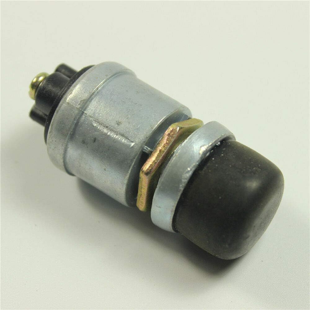
Image: A single push button switch, typically used for manual door or trunk release.
- Wiring and Brackets (2 sets): For door poppers.

Image: Bundles of green and red/black electrical wires with terminal connectors, used for various connections within the kit.
- Additional Wiring and Connectors: As shown in photos.
Image: Assorted wiring harnesses, including those with inline fuse holders and yellow crimp connectors, for electrical connections.
4. Installation (Setup)
Installation of this kit requires knowledge of automotive electrical systems and mechanical skills. If you are not confident in your abilities, seek professional assistance.
4.1 Planning and Preparation
- Review Vehicle Layout: Determine the best locations for mounting the solenoids, keyless entry module, relays, and manual release buttons.
- Shaved Door Handle Integration: For shaved door applications, ensure the door poppers are correctly aligned and secured to push the door open sufficiently. Custom fabrication may be required.
- Cable Routing: Plan the routing of all wiring to avoid interference with moving parts (windows, door mechanisms) and to protect against pinching or abrasion.
4.2 Mounting Components
- Solenoids: Mount the door popper solenoids securely inside the door panel, ensuring the plunger can effectively push the door open when activated. Use the provided brackets and hardware.
- Keyless Entry Module: Mount the module in a dry, secure location, typically under the dashboard or behind a kick panel.
- Relays: Mount relays in a location that is accessible for wiring and protected from moisture.
- Manual Release Buttons: Install the manual release buttons in a discreet but accessible location inside the vehicle.
4.3 Wiring Connections
A detailed wiring diagram specific to your vehicle and the kit's keyless entry module is crucial for correct installation. The following is a general overview:
- Power and Ground: Connect the main power wire (typically red) to a fused constant 12V source and the ground wire (typically black) to a solid chassis ground point.
- Solenoid Connections: Each solenoid requires power through a relay. The keyless entry module will trigger these relays. Connect the solenoid's power wire to the relay's output, and the solenoid's ground wire to chassis ground.
- Relay Wiring: Connect the relays according to the provided wiring diagram. Typically, the keyless entry module provides a negative trigger to the relay, which then switches 12V power to the solenoid.
- Manual Release Buttons: Wire the manual release buttons to trigger the respective door or trunk solenoids, usually through the same relays or dedicated circuits.
- Antenna: Position the keyless entry module's antenna for optimal range, away from metal obstructions.
5. Operation
Once installed and tested, the system operates via the remote key fobs.
- Door Release: Press the designated button on the remote to activate the door popper solenoids. This will push the door open slightly, allowing you to open it manually.
- Trunk/Hatch Release: Press the designated button on the remote to activate the trunk release solenoid, unlatching the trunk or hatch.
- Multiple Channels: The system supports up to five channels, allowing for independent control of two front doors and three additional outputs for other doors, a hatch, or a trunk. Refer to your keyless entry module's specific instructions for programming and channel assignment.
- Manual Override: Use the installed manual push buttons for door or trunk release if the remote is unavailable or the battery is dead.
6. Maintenance
Regular inspection and minor maintenance can prolong the life and ensure reliable operation of your kit.
- Check Connections: Periodically inspect all electrical connections for tightness and corrosion.
- Solenoid Inspection: Check the door popper solenoids and their cables for any signs of wear, fraying, or obstruction. Ensure the anti-scratch tips are intact.
- Remote Battery: Replace the remote key fob battery as needed. Refer to the remote's specific instructions for battery replacement.
- Clean Components: Keep the keyless entry module and other components free from dirt and moisture.
7. Troubleshooting
If you experience issues with your Shaved Door Handle Popper Kit, consider the following troubleshooting steps:
- Remote Not Working:
- Check the remote battery.
- Ensure the keyless entry module is receiving power.
- Verify the remote is programmed correctly to the module.
- Door/Trunk Not Popping:
- Check all wiring connections to the solenoid and relay.
- Verify the relay is functioning correctly (you may hear a click when activated).
- Ensure the solenoid is receiving power when activated.
- Inspect the solenoid plunger and cable for obstructions or damage.
- Check the fuse for the circuit.
- Intermittent Operation:
- Inspect for loose or corroded connections.
- Check for interference with the remote signal (e.g., metal objects near the antenna).
If problems persist after troubleshooting, consult a professional automotive electrician.
8. Specifications
- Model Number:
- 138-SLDPALL
- Type:
- Universal Remote Keyless Entry and Door/Trunk Release System
- Door Popper Solenoid Force:
- 80 lb
- Solenoid Dimensions (approximate):
- 5 1/2 inches (length) x 3 inches (width) x 2 1/2 inches (height)
- Channels:
- 5 total (2 for front doors, 3 additional for other doors/hatch/trunk)
- Relay Rating:
- 12VDC 30/40A
- Compatibility:
- Universal for any make and model vehicle
9. Warranty and Support
As the brand is listed as 'Unknown', specific warranty information is not available in this manual. For any warranty claims, technical support, or replacement parts, please contact the original seller or retailer from whom you purchased this product. Retain your proof of purchase for any support inquiries.