Introduction
The EPEVER EPIPDB-COM Series Dual Battery Solar Charge Controller is designed to efficiently manage the charging of two independent battery banks from a single solar array. This controller is ideal for applications such as RVs, caravans, and boats, where two separate battery systems (e.g., house battery and starter battery) need to be charged simultaneously and independently. It features automatic 12V/24V system voltage recognition and offers various protection functions to ensure safe and reliable operation.
This manual provides detailed instructions for the installation, operation, maintenance, and troubleshooting of your EPIPDB-COM-20 solar charge controller.

The EPEVER EPIPDB-COM-20 Dual Battery Solar Charge Controller, designed for 12V/24V auto-sensing systems.
Safety Information
- Ensure all wiring is correctly polarized before connecting to the controller. Reverse polarity can damage the unit.
- Always connect the battery first, then the solar panel. Disconnect the solar panel first, then the battery.
- Install the controller in a well-ventilated area, away from flammable materials and direct sunlight.
- Do not disassemble or attempt to repair the controller yourself. Refer to qualified personnel for service.
- Ensure proper wire gauge is used for all connections to prevent overheating and voltage drop.
- This controller is designed for use with sealed, gel, and flooded lead-acid batteries. Do not use with other battery types unless specified.
Product Overview
Components and Features
The EPIPDB-COM-20 controller is equipped with various indicators and connection terminals for easy setup and monitoring.

Key components of the EPIPDB-COM controller, including local temperature sensor, battery terminals, PV input, and remote meter connection.
- Local Temperature Sensor: Measures ambient temperature for accurate charging compensation.
- Battery 1 & Battery 2 Indicators: LEDs indicating the status of each battery bank.
- Setting Button: For adjusting battery type, charging priority, and charging frequency.
- PV Input Terminals: Connects to the solar panel array.
- Battery 1 & Battery 2 Output Terminals: Connects to the respective battery banks.
- Remote Temperature Sensor Port: For connecting an optional external temperature sensor (RTS).
- Remote Meter Connection Port: For connecting an optional remote meter (e.g., MT-1) for detailed monitoring and control.
Key Features:
- Built-in short-circuit protection, open-circuit protection, reverse protection, and over-load protection.
- Designed to charge and protect two batteries or battery banks independently with adjustable charging priority (e.g., 30%/70%).
- Automatic temperature compensation: If no Remote Temperature Sensor (RTS) is connected, the controller uses data from the local temperature sensor. The controller will automatically switch to RTS data when an RTS is connected.
- Adjustable controlling parameters for the system, easy to set up and operate.
- Supports various types of batteries: sealed, gel, and flooded.
- Suitable for motorhomes, caravans, boats, or any system with two 12V / 24V batteries or battery banks.

The controller features a robust aluminum alloy construction for efficient heat dissipation.
Setup and Installation
Wiring Diagram
Follow the wiring diagram below for proper connection of the solar panel and batteries to the controller. Ensure all connections are secure and correctly polarized.

Typical wiring setup for the EPIPDB-COM controller in a dual-battery system, such as in a golf cart.
Connection Steps:
- Connect Battery 1: Connect the positive and negative terminals of Battery 1 to the corresponding 'Battery 1' terminals on the controller.
- Connect Battery 2: Connect the positive and negative terminals of Battery 2 to the corresponding 'Battery 2' terminals on the controller.
- Connect Solar Panel: Connect the positive and negative terminals of your solar panel(s) to the 'PV' input terminals on the controller.
- Optional Connections:
- Remote Temperature Sensor: If using an external remote temperature sensor (not included), connect it to the 'remote temp. sensor' port.
- Remote Meter: If using a remote meter like the MT-1 (not included), connect it to the 'remote meter. connection' port using an RJ45 cable.

Optional connections for enhanced monitoring and temperature compensation.
Operating Instructions
The EPIPDB-COM controller allows for customization of battery type, charging priority, and charging frequency. These settings are adjusted using the button on the controller's interface.
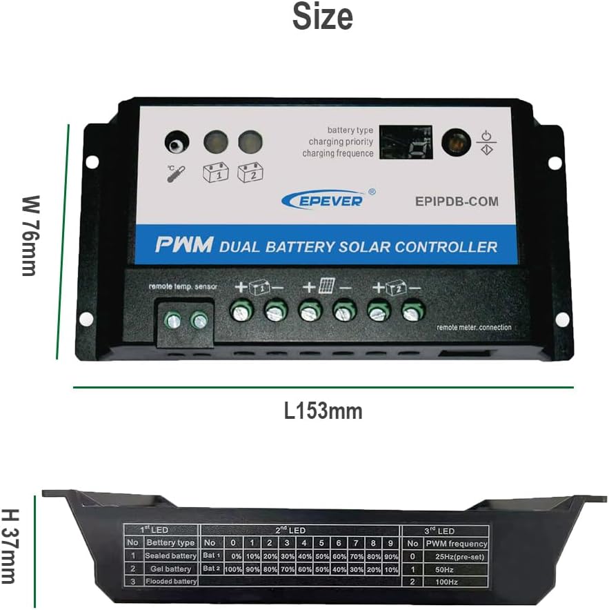
The controller's interface allows for setting battery type, charging priority, and charging frequency. Refer to the table on the image for LED indicator meanings.
Setting Parameters:
- Battery Type: Select the appropriate battery type (Sealed, Gel, or Flooded) to ensure optimal charging algorithms.
- Charging Priority: Adjust the charging ratio between Battery 1 and Battery 2. For example, a 30%/70% setting means 30% of the charging current goes to Battery 1 and 70% to Battery 2. When one battery is fully charged, the remaining current will be diverted to the other battery.
- Charging Frequency: This setting relates to the PWM charging frequency.
Consult the detailed instructions provided with the product packaging for specific button press sequences to adjust these parameters.
Maintenance
To ensure the longevity and optimal performance of your EPEVER solar charge controller, regular maintenance is recommended:
- Cleanliness: Keep the controller clean and free from dust and debris. Use a dry cloth for cleaning.
- Connections: Periodically check all wiring connections to ensure they are tight and free from corrosion. Loose connections can lead to voltage drops and overheating.
- Ventilation: Ensure the installation area remains well-ventilated to prevent overheating of the controller.
- Environmental Conditions: Protect the controller from direct water exposure, extreme temperatures, and high humidity.
Troubleshooting
This section provides solutions to common issues you might encounter with your solar charge controller.
| Symptom | Possible Cause | Solution |
|---|---|---|
| LED blinking rapidly | Short circuit detected (PV or battery) | Check PV and battery connections to ensure correct polarity and no short circuits. |
| LED slowly flashing | Battery is fully charged | This is normal operation. No action required. |
| LED is ON (solid) | Controller is actively charging | This is normal operation. No action required. |
| LED flashing frequently | Battery connected, but no charging occurring | Check solar panel connection, ensure sufficient sunlight, and verify PV voltage. |
| LED is OFF | No battery connected or over voltage condition | Ensure battery is properly connected. Check battery voltage to ensure it's within the controller's operating range. |
Specifications
Technical specifications for the EPEVER EPIPDB-COM-20 Dual Battery Solar Charge Controller.
| Specification | Value |
|---|---|
| Model | EPIPDB-COM-20 |
| Rated Charge Current | 20A |
| System Voltage | 12V/24V Auto Work |
| Display Type | LED |
| Supported Battery Types | Sealed, Gel, Flooded |
| Manufacturer | EPEVER |
| Material | Plastic (with Aluminum Alloy heat sink) |
| Item Weight | 8.8 ounces (250 Grams) |
| Package Dimensions | 6.38 x 3.54 x 1.73 inches |
| UPC | 732376583541 |
Warranty and Support
EPEVER products are designed for reliability and performance. For specific warranty details, please refer to the warranty card included with your product or visit the official EPEVER website.
For technical support, troubleshooting assistance, or inquiries regarding product selection and compatibility, you may contact SolaMr, an authorized distributor of EPEVER products. Their contact information can typically be found on their official website or through your purchase platform.


