
1. Introduction
The DollaTek NE555 Pulse Frequency Duty Cycle Adjustable Module is a versatile square wave signal generator designed for various electronic applications. It can be used for experimental development, driving stepper motors, generating adjustable pulses for microcontrollers (MCUs), and controlling associated circuitry. This module provides adjustable frequency and duty cycle outputs, making it suitable for a wide range of projects.
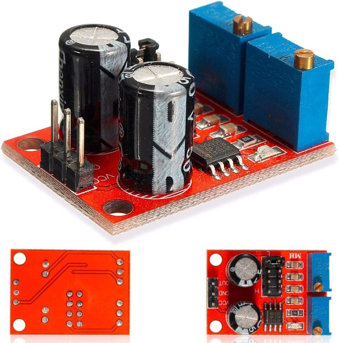
Figure 1: Overview of the DollaTek NE555 Pulse Frequency Duty Cycle Adjustable Module.
2. Key Features
- Main chip: NE555 timer IC.
- Input Voltage: DC 5V to 15V.
- Output Amplitude: 4.2V V-PP (with 5V input) to 11.4V V-PP (with 12V input).
- Four selectable output frequency ranges: 1Hz-50Hz, 50Hz-1KHz, 1KHz-10KHz, 10KHz-200KHz.
- Adjustable output duty cycle via variable resistors.
- Output LED indicator: Flashes at low frequency, on for low level, off for high level.
- Compact size: Approximately 31mm x 22mm.
3. Setup and Connections
This section details how to properly connect and prepare your NE555 module for operation.
3.1 Power Supply Connection
Connect the module to a DC power source within the specified voltage range.
- VCC: Connect to the positive (+) terminal of your DC power supply (5V to 15V).
- GND: Connect to the negative (-) terminal of your DC power supply.
Ensure the input current is at least 100mA for stable operation.
3.2 Output Connection
The square wave signal is available at the OUT pin.
- OUT: Connect this pin to the input of the circuit or device you wish to control or test.
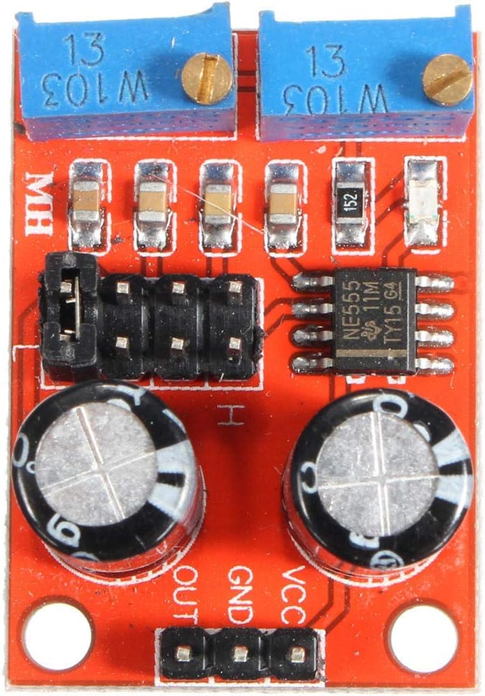
Figure 2: Top view of the module, highlighting connection points and the NE555 chip.
4. Operating Instructions
The module features jumpers for frequency range selection and potentiometers for fine-tuning the duty cycle.
4.1 Frequency Range Selection
The module has four selectable frequency ranges, controlled by onboard jumpers. Adjust the jumpers to select the desired range:
- LF (Low Frequency) file: 1Hz ~ 50Hz
- IF (Intermediate Frequency) file: 50Hz ~ 1kHz
- High-frequency file: 1KHz ~ 10kHz
- HF (High Frequency) file: 10kHz ~ 200kHz
Refer to the module's markings for specific jumper configurations for each range.
4.2 Duty Cycle Adjustment
The output duty cycle can be fine-tuned using the two variable resistors (potentiometers) on the module. Rotate these potentiometers with a small screwdriver to adjust the pulse width.
Note: The duty cycle and frequency are not independently adjustable. Adjusting the duty cycle will cause a change in the output frequency.
4.3 Output LED Indicator
The module includes an LED indicator for visual feedback:
- When the output is at a low level, the LED will illuminate.
- When the output is at a high level, the LED will turn off.
- At low frequencies, the LED will visibly flash, indicating the pulse output.
5. Specifications
| Parameter | Value |
|---|---|
| Main Chip | NE555 |
| Input Voltage | DC 5V - 15V |
| Input Current | ≥100 mA |
| Output Amplitude (5V input) | 4.2V V-PP |
| Output Amplitude (12V input) | 11.4V V-PP |
| Max Output Current (5V supply) | ≥15mA (V-PP > 50%) |
| Max Output Current (12V supply) | ≥35mA (V-PP > 50%) |
| Frequency Ranges | 1Hz-50Hz, 50Hz-1KHz, 1KHz-10KHz, 10KHz-200KHz |
| Module Dimensions | 31mm x 22mm x 14mm (approx.) |
| Manufacturer | DollaTek |
| ASIN | B081JPC7DT |
| UPC | 725835040495 |
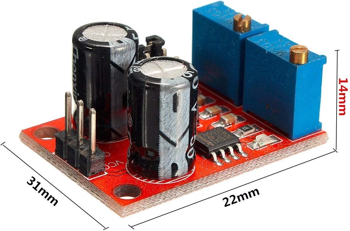
Figure 3: Module dimensions for integration planning.
6. Maintenance
The DollaTek NE555 module is designed for durability and requires minimal maintenance. Follow these guidelines to ensure its longevity:
- Handling: Always handle the module by its edges to avoid touching components, especially the exposed pins, which can be sensitive to electrostatic discharge.
- Cleaning: If necessary, gently clean the module with a soft, dry brush or compressed air to remove dust. Avoid using liquids or abrasive cleaners.
- Storage: Store the module in a dry, cool environment, away from direct sunlight and extreme temperatures.
- Power Off: Disconnect power before making any changes to connections or adjustments to prevent accidental short circuits or damage.
7. Troubleshooting
If you encounter issues with your NE555 module, consider the following common problems and solutions:
- No Output Signal:
- Verify that the power supply is connected correctly (VCC and GND) and within the 5V-15V DC range.
- Check all connections for continuity and proper seating.
- Ensure the input current meets the minimum requirement of ≥100mA.
- Incorrect Frequency or Duty Cycle:
- Confirm that the correct frequency range jumper is selected.
- Adjust the potentiometers slowly to fine-tune the frequency and duty cycle. Remember that adjusting the duty cycle will affect the frequency.
- Ensure the capacitors are correctly installed and not damaged, as their capacity determines the frequency range.
- LED Indicator Not Functioning:
- If the LED is always off, check for a valid output signal with an oscilloscope or multimeter. If there is an output, the LED itself might be faulty.
- If the LED is always on, the output might be stuck at a low level. Check for short circuits or component damage.
- Module Overheating:
- Ensure the input voltage does not exceed 15V.
- Verify that the output load does not draw excessive current beyond the module's maximum output current capabilities.
8. Warranty and Support
For warranty information or technical support regarding your DollaTek NE555 Pulse Frequency Duty Cycle Adjustable Module, please refer to the retailer where the product was purchased or contact DollaTek customer service directly through their official website or provided contact channels. Please have your product model and purchase details ready when seeking support.