
1. Introduction
This manual provides detailed instructions for the installation, operation, and maintenance of the DollaTek 1803BW DC PWM Motor Speed Controller. This compact and efficient module is designed to control the speed of low-voltage DC motors by adjusting the Pulse Width Modulation (PWM) signal. It is suitable for various applications requiring precise motor speed regulation.
2. Features
- PWM Speed Control: Controls DC motor speed by adjusting the Pulse Width Modulation.
- Wide Voltage Range: Compatible with input voltages from 1.8V DC to 15V DC.
- Current Capacity: Supports currents up to 2 Amperes.
- Overcurrent Protection: Integrated 2A fuse provides protection against excessive current. The fuse is designed to reset automatically once cooled after an overcurrent event.
- Compact Design: Small dimensions (32 x 32 x 14 mm) for easy integration into projects.
- External Potentiometer Connection: Designed for connection with an external potentiometer for speed adjustment (potentiometer not included with the module itself, but shown in some product images as an example of use).
3. Specifications
| Parameter | Value |
|---|---|
| Input Voltage | DC 1.8V - 15V |
| Maximum Current | 2A |
| Dimensions (L x W x H) | 32 mm x 32 mm x 14 mm |
| Overcurrent Protection | 2A resettable fuse |
| Control Method | Pulse Width Modulation (PWM) |
4. Package Contents
- DollaTek 1803BW DC PWM Motor Speed Controller Module (Quantity: 2, as per product description)
Note: Potentiometer for speed adjustment is typically sold separately or connected externally.
5. Safety Information
Please read and understand all safety instructions before using this product. Failure to follow these instructions may result in electric shock, fire, or serious injury.
- Ensure the input voltage and current do not exceed the specified limits (DC 1.8V-15V, 2A).
- Always disconnect power before making any connections or disconnections.
- Avoid short circuits between terminals.
- Do not expose the module to moisture, extreme temperatures, or corrosive environments.
- This product is not a toy. Keep out of reach of children.
- If the module shows signs of damage or malfunction, discontinue use immediately.
6. Setup and Installation
The DollaTek 1803BW controller features clear markings for power input and motor output connections. Refer to the diagrams below for proper wiring.

Figure 6.1: Top view of the controller module, highlighting the main components and connection points.
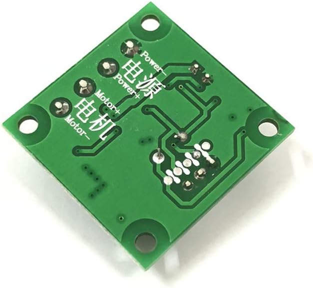
Figure 6.2: Bottom view of the controller module, indicating the power input and motor output solder pads. The labels 'Power+' and 'Power-' are for the DC power supply, and 'Motor+' and 'Motor-' are for the DC motor connections.
6.1 Wiring Connections
- Power Input: Connect your DC power supply (1.8V to 15V) to the terminals labeled "Power+" and "Power-". Ensure correct polarity.
- Motor Output: Connect your DC motor to the terminals labeled "Motor+" and "Motor-". The polarity for the motor connections will determine the direction of rotation.
- Potentiometer Connection: The module includes a 3-pin header for connecting an external potentiometer (typically 10KΩ linear taper). Connect the potentiometer's outer pins to the module's outer pins on the 3-pin header, and the potentiometer's wiper (middle pin) to the module's middle pin.

Figure 6.3: Example of the controller module connected to an external potentiometer for speed adjustment. The potentiometer allows for variable resistance to control the PWM signal.
6.2 Mounting
The module has four mounting holes in its corners, allowing it to be securely fastened to a project enclosure or PCB using small screws (not included).
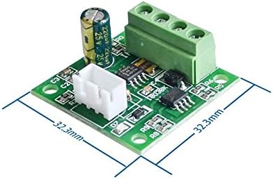
Figure 6.4: Dimensions of the controller module, showing its compact size and the location of mounting holes.
7. Operating Instructions
- Power On: After ensuring all connections are correct and secure, apply power to the "Power+" and "Power-" terminals.
- Adjust Speed: Use the connected external potentiometer to adjust the motor speed. Turning the potentiometer knob will vary the PWM duty cycle, thereby changing the average voltage supplied to the motor and controlling its speed.
- Power Off: To stop the motor and power down the module, disconnect the main DC power supply.
Note: This module does not include an on/off switch. Power control must be managed externally.
8. Maintenance
- Keep the module clean and free from dust and debris.
- Periodically check all connections for tightness and ensure there are no loose wires.
- Avoid physical impact or excessive force on the module.
- If the resettable fuse trips due to overcurrent, disconnect power, identify and resolve the cause of the overcurrent, and allow the fuse to cool and reset before reapplying power.
9. Troubleshooting
| Problem | Possible Cause | Solution |
|---|---|---|
| Motor does not run. | No power, incorrect wiring, faulty motor, potentiometer at minimum setting. | Check power supply, verify all connections, test motor independently, adjust potentiometer. |
| Motor runs at full speed regardless of potentiometer. | Potentiometer not connected correctly or faulty. | Ensure potentiometer is wired correctly (3 pins), test potentiometer. |
| Motor runs intermittently or stops. | Loose connections, overcurrent protection triggered, insufficient power supply. | Check all wiring, reduce motor load, ensure power supply can deliver sufficient current. Allow fuse to reset if tripped. |
| Module gets excessively hot. | Overload, short circuit, operating outside specifications. | Reduce motor load, check for short circuits, ensure input voltage and current are within limits. |
10. Warranty and Support
DollaTek products are designed for reliability and performance. For specific warranty information, please refer to the documentation provided at the time of purchase or contact your retailer. For technical support, please reach out to DollaTek customer service through their official website or your point of purchase.
