1. Introduction
This manual provides detailed instructions for the installation, operation, and maintenance of the Antkay NVEM 5-Axis CNC Controller Ethernet MACH3 USB Interface Board. This controller is designed to facilitate precise control of CNC engraving and stepping motor systems, offering reliable performance through its Ethernet and MACH3 compatibility. Please read this manual thoroughly before using the product to ensure safe and efficient operation.
2. Safety Information
Always prioritize safety when working with CNC machinery. Failure to follow safety guidelines can result in personal injury or damage to equipment.
- Power Supply: Ensure the power supply voltage (12-32V DC) matches the controller's requirements. Incorrect voltage can damage the board.
- Emergency Stop: Always have an easily accessible emergency stop button wired to the controller. Test its functionality regularly.
- Wiring: All wiring should be performed by qualified personnel. Ensure all connections are secure and correctly polarized.
- Grounding: Proper grounding of the CNC machine and controller is essential to prevent electrical hazards and interference.
- Moving Parts: Keep hands and loose clothing away from moving parts of the CNC machine during operation.
- Environment: Operate the controller in a clean, dry environment, free from excessive dust, moisture, and extreme temperatures.
3. Product Overview
The Antkay NVEM 5-Axis CNC Controller is a high-performance interface board designed for MACH3 software. It supports up to 5 axes of motion control with a 200KHz pulse output frequency, communicating via Ethernet for stable and fast data transmission.
3.1 Key Components and Ports
The board features various terminal blocks for connecting power, stepper motors, input devices (e.g., limit switches, probes), and output devices (e.g., spindle control, relays).

Figure 3.1: Top-down view of the NVEM 5-axis CNC controller board, showing all terminal blocks and labels for various connections.

Figure 3.2: Slightly angled top-down view of the NVEM board, providing a general perspective of its layout and port arrangement.
- 12-32V IN: Power input terminal.
- Stepper Motor Control Port: Terminals for X, Y, Z, A, B, C axes.
- Spindle: Spindle control output.
- Input Port: Terminals for various input signals (e.g., limit switches, E-stop, probe).
- Output Port: Terminals for general-purpose outputs.
- MPG: Manual Pulse Generator connection.
- Ethernet Port: RJ45 connector for network communication with the PC.
4. Setup
4.1 Hardware Installation
Before connecting any components, ensure the power supply is disconnected.
- Mounting: Securely mount the NVEM board within your control enclosure using appropriate standoffs and screws.
- Power Connection: Connect a 12-32V DC power supply to the '12-32V IN' terminal block. Observe correct polarity (+ and -).
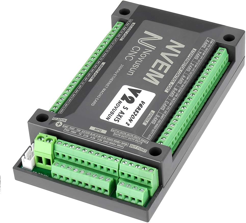
Figure 4.1: Angled view of the NVEM board, showing the 12-32V power input terminal and adjacent output terminals.
- Stepper Motor Connections: Connect your stepper motor drivers to the 'STEPPERMOTOR CONTROL PORT' terminals. Each axis (X, Y, Z, A, B, C) has dedicated terminals for pulse (PUL), direction (DIR), and enable (ENA) signals. Refer to your motor driver's manual for specific wiring.

Figure 4.2: Angled view of the NVEM board, emphasizing the 'STEPPERMOTOR CONTROL PORT' terminal blocks for X, Y, Z, A, B, C axes.
- Input Device Connections: Connect limit switches, home switches, E-stop buttons, and probes to the 'INPUT PORT' terminals. Ensure proper wiring for normally open (NO) or normally closed (NC) configurations as required by your setup.

Figure 4.3: Angled view of the NVEM board, focusing on the 'INPUT PORT' terminal block on the right side.
- Output Device Connections: Connect spindle control signals or other auxiliary outputs to the 'OUTPUT PORT' terminals.

Figure 4.4: Angled view of the NVEM board, showing the 'OUTPUT PORT' terminal block on the top right.
- Ethernet Connection: Connect the NVEM board to your PC using a standard Ethernet cable. Ensure your PC's network adapter is configured for the correct IP address range.

Figure 4.5: Angled view of the NVEM board, highlighting the Ethernet port on the left side for PC connection.

Figure 4.6: A standard grey Ethernet cable, typically used for connecting the controller to a computer.
4.2 Software Configuration (MACH3)
The NVEM controller requires MACH3 software for operation. Ensure MACH3 is installed on your PC.
- Driver Installation: Install the necessary NVEM plugin for MACH3. This typically involves copying a DLL file to the MACH3 plugins folder. Refer to the specific NVEM driver documentation for exact steps.
- MACH3 Configuration:
- Open MACH3 and navigate to Config > Ports and Pins.
- Configure the motor outputs, input signals (limit switches, E-stop), and output signals (spindle, relays) according to the NVEM board's pinout diagram.
- Set up motor tuning parameters (steps per unit, velocity, acceleration) for each axis based on your stepper motors and mechanical setup.
- Configure spindle control settings if applicable.
- Network Settings: Ensure the IP address of the NVEM board is correctly configured in the MACH3 plugin settings and matches your PC's network configuration.
5. Operating Instructions
Once hardware and software are configured, you can begin operating your CNC machine.
- Power On: Turn on the power supply to the NVEM board and then launch MACH3 on your PC.
- Homing: Perform a homing sequence (if configured) to establish the machine's absolute zero position.
- Jogging: Use the manual jog controls in MACH3 or an MPG (Manual Pulse Generator) to move the axes and verify motor functionality.
- Load G-code: Load your desired G-code program into MACH3.
- Set Work Offset: Define your work coordinate system (G54, G55, etc.) by setting the X, Y, Z zero points for your material.
- Start Program: Initiate the G-code program. Monitor the machine closely during the initial run.
- Emergency Stop: In case of any malfunction or unsafe condition, immediately press the emergency stop button.
6. Maintenance
Regular maintenance ensures the longevity and reliable performance of your NVEM controller.
- Cleaning: Periodically clean the board and its enclosure to remove dust and debris. Use compressed air or a soft brush. Ensure power is off before cleaning.
- Connection Checks: Regularly inspect all wiring connections for looseness or corrosion. Tighten any loose terminals.
- Environmental Control: Maintain a stable operating environment, avoiding extreme temperatures and humidity.
7. Troubleshooting
This section addresses common issues you might encounter.
| Problem | Possible Cause | Solution |
|---|---|---|
| Motors not moving | No power to board/drivers; incorrect wiring; MACH3 not configured; E-stop engaged. | Check power supply; verify all wiring; review MACH3 motor tuning and pin settings; disengage E-stop. |
| Communication error with PC | Incorrect IP address; faulty Ethernet cable; network adapter issues. | Verify NVEM and PC IP addresses; replace Ethernet cable; check PC network settings. |
| Limit switch not responding | Incorrect wiring; MACH3 pin configuration error; faulty switch. | Check limit switch wiring (NO/NC); verify MACH3 input pin settings; test switch continuity. |
| Spindle not turning on/off | Incorrect wiring; MACH3 spindle configuration error; faulty relay/VFD. | Check spindle control wiring; verify MACH3 output pin settings; test relay/VFD. |
8. Specifications
- Model: NVEM 5-Axis CNC Controller
- Axes Supported: 5-Axis
- Communication Interface: Ethernet
- Pulse Output Frequency: 200KHz
- Compatible Software: MACH3
- Input Voltage: 12-32V DC
- Input Ports: Multiple configurable digital inputs
- Output Ports: Multiple configurable digital outputs
9. Warranty and Support
This product is covered by a standard manufacturer's warranty against defects in materials and workmanship. For specific warranty terms and conditions, please refer to the product packaging or contact your retailer.
For technical support, troubleshooting assistance, or inquiries regarding product functionality, please contact the vendor or manufacturer through the contact information provided at the point of purchase. When contacting support, please have your product model and purchase details available.