Product Overview
The TOPRING 51.425 AIRFLO 400 is a compact, integrated Filter-Regulator (F/R) and Lubricator (L) unit designed for air compressor systems. This Series 51 unit features accurate pressure control with minimal drift, a semi-automatic drain, and lubrication proportioned to airflow. It is engineered for efficiency and ease of use in various industrial and home improvement applications.
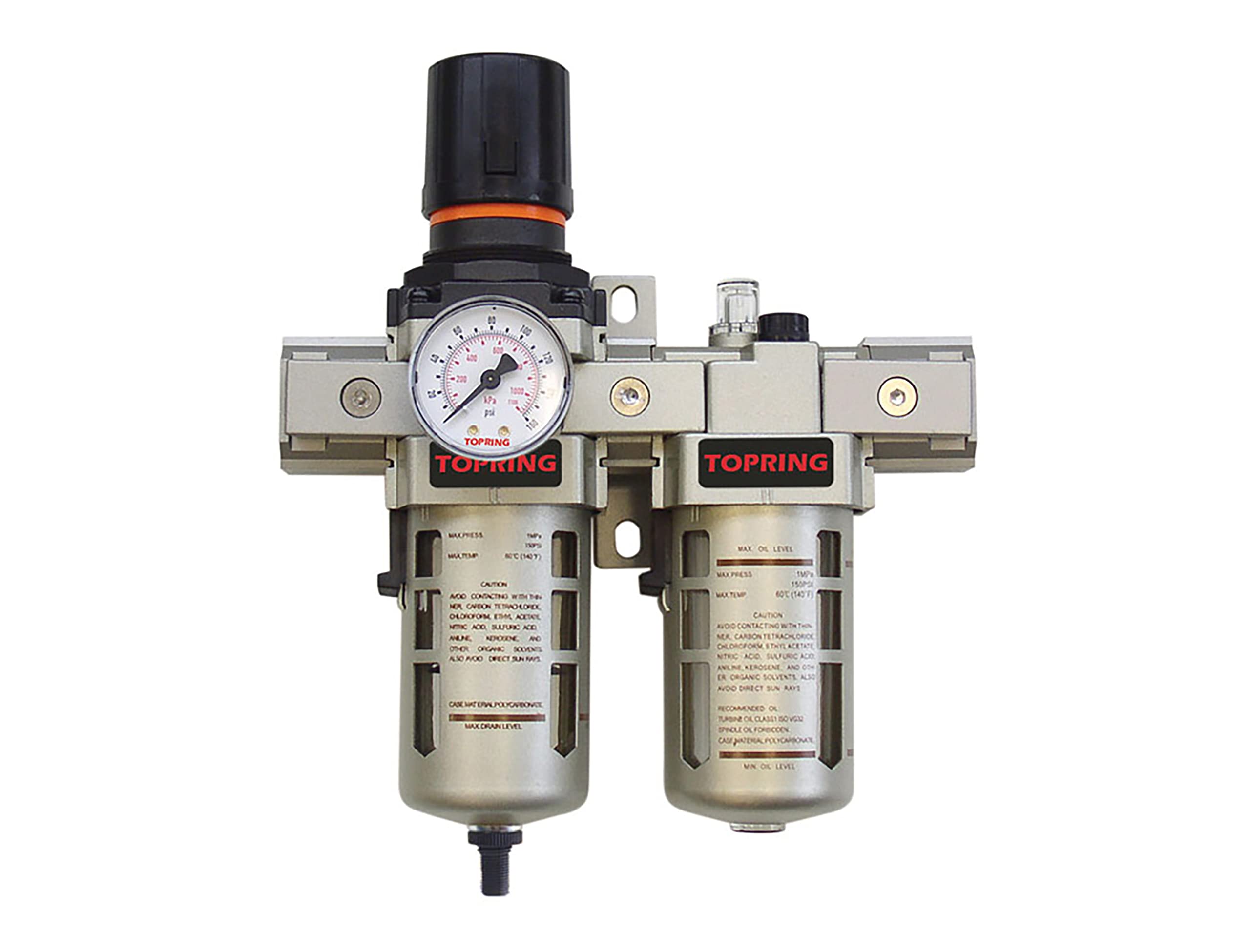
An image showing the TOPRING 51.425 AIRFLO 400 integrated filter-regulator combo and lubricator. The unit features a pressure gauge on the filter-regulator section and a transparent bowl for the lubricator, allowing visibility of the oil level. Both sections have clear markings for maximum pressure, temperature, and warnings regarding contact with certain chemicals. The semi-automatic drain is visible at the bottom of the filter section.
Key features include a removable locking push-pull adjusting knob for pressure regulation, a standard semi-automatic drain that requires a simple tug of the ring to drain accumulated moisture, and a lubricator that proportions oil based on airflow. The unit comes complete with a pressure gauge, piping adapters, and a mounting bracket for convenient installation.
Setup and Installation
Unpacking
- Carefully remove the unit and all components from the packaging.
- Verify that all included items are present: the F/R+L unit, pressure gauge, modular piping adapters, and mounting bracket.
- Inspect the unit for any signs of shipping damage. Do not install if damage is observed.
Mounting
Mount the unit vertically in a location that is easily accessible for operation and maintenance. Ensure the mounting surface is stable and can support the weight of the unit when full. Use the provided mounting bracket to secure the unit firmly.
Connecting Air Lines
- The unit has 1/2 (F) NPT port sizes. Ensure your air lines and fittings match this size.
- Connect the incoming air supply to the inlet port (typically marked 'IN' or with an arrow indicating flow direction).
- Connect the outgoing air line to the outlet port (typically marked 'OUT' or with an arrow).
- Use thread sealant tape or compound on all threaded connections to ensure an airtight seal.
- Install the pressure gauge into its designated 1/4 (F) NPT port on the regulator section.
Operation
Adjusting Pressure
- To adjust the regulated pressure, pull the adjusting knob upwards to unlock it.
- Turn the knob clockwise to increase pressure and counter-clockwise to decrease pressure.
- Monitor the pressure gauge to set the desired output pressure within the 5-125 PSI range.
- Once the desired pressure is set, push the knob downwards to lock it in place.
Lubricator Adjustment
- The lubricator proportions oil to the airflow. The oil drip rate can be adjusted via the screw on top of the lubricator.
- Turn the adjustment screw to increase or decrease the oil drip rate, observing the sight glass for the drip.
- Adjust the rate according to the requirements of your pneumatic tools or equipment.
Drain Operation
- The filter section is equipped with a semi-automatic drain.
- To drain accumulated moisture, simply tug the ring at the bottom of the filter bowl.
- Drain regularly, especially in humid environments, to prevent water from entering your air tools.
Maintenance
Filter Element Replacement
- Depressurize the air system before attempting any maintenance.
- Unscrew the filter bowl from the main body.
- Remove the old filter element and replace it with a new 5-micron element.
- Ensure the O-rings are properly seated and lubricated before reassembling the bowl.
Lubricator Refill
- Depressurize the air system.
- Unscrew the lubricator bowl from the main body.
- Fill the bowl with recommended oil, such as Turbine Oil Class 50VG or Spindle Oil Food Grade, up to the MAX OIL LEVEL mark (130ml capacity).
- Avoid overfilling.
- Ensure the O-rings are properly seated and lubricated before reassembling the bowl.
Bowl Cleaning
- The bowls are made of polycarbonate. CAUTION: Avoid contacting with chemicals such as carbon tetrachloride, chloroform, ethyl acetate, nitric acid, sulfuric acid, aniline, kerosene, and other organic solvents. These can damage the bowl.
- Clean bowls with warm soapy water only. Rinse thoroughly and dry before reassembly.
- Avoid direct sun rays on the bowls as this can also cause damage.
Troubleshooting
| Problem | Possible Cause | Solution |
|---|---|---|
| No airflow or low pressure output | Inlet pressure too low; Regulator knob locked in low position; Clogged filter element. | Check compressor output; Unlock and adjust regulator knob; Replace filter element. |
| Excessive oil in air line | Lubricator adjustment too high; Incorrect oil type. | Reduce lubricator drip rate; Use recommended oil. |
| Water in air tools | Filter drain not operated regularly; High humidity. | Drain filter bowl frequently; Consider adding an air dryer upstream. |
| Air leaks around unit | Loose fittings; Damaged O-rings or seals. | Tighten all connections; Inspect and replace O-rings/seals if damaged. |
Technical Specifications
| Feature | Value |
|---|---|
| Model | 51.425 |
| Port Size | 1/2 (F) NPT |
| Pressure Range | 5-125 PSI |
| Maximum Airflow at 100 PSI | 105 SCFM |
| Maximum Working Pressure | 150 PSI |
| Working Temperature | 5 to 60 °C (41 to 140 °F) |
| Pressure Gauge Port Size | 1/4 (F) NPT |
| Centrifugal Filtration | 5 micron |
| Filter Bowl Capacity | 45ml |
| Lubricator Capacity | 130ml |
| Included Components | Modular Piping Adapters, Pressure Gauge, Mounting Bracket |
Warranty and Support
Warranty Information
TOPRING products are manufactured to high-quality standards and are covered by a manufacturer's warranty against defects in materials and workmanship. For specific warranty terms and conditions, please refer to the documentation provided with your purchase or contact TOPRING customer support directly.
Customer Support
For technical assistance, parts, or service inquiries, please contact TOPRING directly:
TOPRING
Granby, QC, Canada
Please have your model number (51.425) and purchase information ready when contacting support.