1. Introduction
The XYGStudy MLX90640-D55 is a 32x24 pixel IR array thermal imaging camera module designed for high-precision non-contact temperature measurements. It communicates via an I2C interface and is compatible with 3.3V/5V operating voltages, supporting various host platforms such as Raspberry Pi, Arduino (ESP32), and STM32.
This module utilizes the MLX90640 far-infrared thermal sensor array to detect the IR distribution of objects within its field of view. It processes this data to calculate surface temperatures and generate thermal images. Its compact form factor makes it suitable for integration into diverse industrial and intelligent control applications.

Figure 1: The MLX90640-D55 Thermal Camera Module.
2. Key Features
- Adopts MLX90640 far-infrared thermal sensor array with 32x24 pixels.
- Communicates via I2C interface, configurable to fast mode (up to 1MHz data rate).
- Noise Equivalent Temperature Difference (NETD) of 0.1K RMS @1Hz refresh rate.
- Onboard voltage translator ensures compatibility with 3.3V/5V operating voltage.
- Comes with development resources and manual, including examples for Raspberry Pi, Arduino (ESP32), and STM32.

Figure 2: Overview of MLX90640-D55 features and capabilities.
3. Specifications
| Specification | Value |
|---|---|
| Operating Voltage | 3.3V/5V |
| Operating Current | <23mA |
| Communication Interface | I2C (address 0x33) |
| Field of View (Horizontal×Vertical) | 55°×35° (narrow angle FOV, suitable for long-range measuring) |
| Operating Temperature | -40℃~85℃ |
| Target Temperature | -40℃~300℃ |
| Resolution | ±1℃ |
| Refresh Rate | 0.5Hz~64Hz (programmable) |
| Dimensions | 28mm×16 mm |
| Mounting Hole Size | 2.0mm |
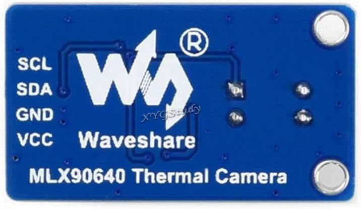
Figure 3: Detailed specifications of the MLX90640-D55 module.
4. Pinouts
The MLX90640-D55 module features a standard pinout for easy integration with microcontrollers (MCUs). The connections are as follows:
- VCC ↔ 3.3V / 5V (Power Supply)
- GND ↔ GND (Ground)
- SDA ↔ MCU.I2C data line
- SCL ↔ MCU.I2C clock line

Figure 4: Pinout diagram for connecting the MLX90640-D55 to a microcontroller.
5. Setup and Connections
To begin using your MLX90640-D55 thermal camera, follow these general setup guidelines:
5.1 Physical Connection
Connect the module to your chosen microcontroller (e.g., Raspberry Pi, ESP32, STM32) using the provided PH2.0 4PIN wire. Ensure correct polarity and pin assignments as detailed in the Pinouts section.

Figure 5: The MLX90640-D55 module connected with its 4-pin wire.
5.2 Module Orientation
Observe the module's orientation for proper integration into your project. The thermal sensor lens should face the area you intend to measure.

Figure 6: Top view of the module.
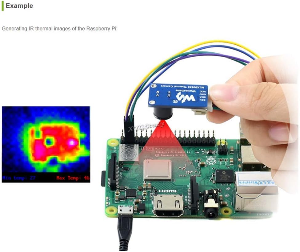
Figure 7: Bottom view of the module.
6. Operating Instructions
6.1 Powering the Device
The module operates on 3.3V or 5V. Ensure your power supply matches the module's requirements. The onboard 3.7V MX1.25 lithium battery charging and discharging interface supports flexible power supply solutions, extending the device's operational time.
6.2 Communication
Communication with the host MCU is established via the I2C interface. The I2C address is 0x33. The interface can be configured to fast mode, supporting data rates up to 1MHz.
6.3 Thermal Imaging
The module captures thermal data within a 55°×35° field of view, suitable for long-range measurements. It can detect target temperatures from -40℃ to 300℃ with a resolution of ±1℃. The refresh rate is programmable from 0.5Hz to 64Hz.
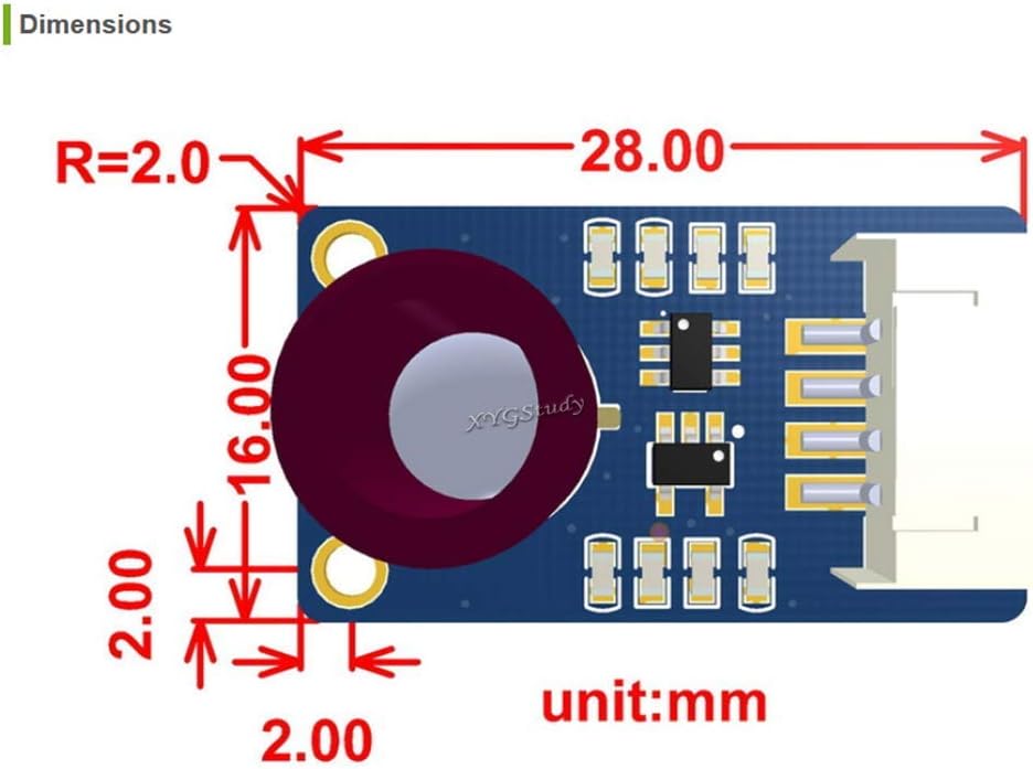
Figure 8: An example of thermal imaging data displayed on a screen.
6.4 Real-time Temperature Measurement Workstation
The device supports TCP/IP wired transmission, allowing for the establishment of a real-time temperature measurement workstation by connecting directly via USB to a Windows system. This enables detailed analysis and monitoring of thermal data.
Video 1: Demonstration of the Thermal 45 or 90 Camera ESP32 Module, showcasing its features and real-time thermal imaging capabilities.
7. Applications
The MLX90640-D55 thermal camera module is versatile and can be used in a wide range of applications, including:
- High-precision non-contact temperature measurements.
- IR thermal imaging devices and IR thermometers.
- Smart home systems, intelligent building management, and intelligent lighting.
- Industrial temperature control and security monitoring.
- Intruder and movement detection systems.
8. Dimensions
The compact design of the MLX90640-D55 module allows for easy integration into various projects. The module's dimensions are 28mm x 16mm, with a mounting hole size of 2.0mm.

Figure 9: Detailed dimensions of the MLX90640-D55 module in millimeters.
9. Maintenance
The onboard RGB LED indicator provides real-time operational status of the module, facilitating equipment monitoring and maintenance. Regularly check the indicator for any unusual patterns that might suggest a malfunction.
Keep the thermal sensor lens clean and free from dust or debris to ensure accurate temperature readings. Use a soft, lint-free cloth for cleaning.
10. Troubleshooting
If you encounter issues with the MLX90640-D55 module, consider the following basic troubleshooting steps:
- Power Supply: Verify that the module is receiving the correct operating voltage (3.3V or 5V) and that the current supply is stable.
- Connections: Double-check all wiring, especially the I2C data and clock lines, for secure and correct connections.
- I2C Communication: Ensure your microcontroller's I2C bus is properly configured and that the module's address (0x33) is correctly used in your code.
- Software/Firmware: Confirm that the correct drivers and libraries are installed and that your code is compatible with the module. Refer to the development resources for examples.
- Environmental Factors: Extreme temperatures or strong electromagnetic interference can affect performance. Operate the module within its specified operating temperature range.
11. Support and Resources
For additional resources, development examples, datasheets, or further assistance, please contact XYGStudy via Amazon message. They will provide the necessary attachments and support to help you get started and resolve any issues.